Facebook
 Google
 GitHub
 Linkedin
Hello friends
I've been trying to wrap my head around the clamper circuit chapter in the ebook for a week now, and I still don't get it. I also tried other sources on the internet to no avail. I'm not sure I understand why the diode does what it does in this circuit. To me it just looks like a high-pass filter with a diode added across the load.
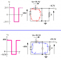
Can someone break down the first 2 cycles in the below diagram in 90° resolution please? from 0-720° (V-out in the first cycle looks as usual) first let's assume that V source has 5v/-5v peaks and to simplify things let's assume an ideal diode with 0 Vf. I also assume that the charge/discharge time of the capacitor is << AC cycle

Here is what I understand and please let me know where I'm wrong.
between 0-90° the diode is forward biased and acts as a short circuit and conducts. The capacitor charges to it's 5v peak.
Between 90-180° the diode still conducts but the capacitor starts to discharge CLOCKWISE to counteract the descending voltage (Am I right so far? does the capacitor really discharge at this point and does it discharge CLOCKWISE?)
between 180-270 is where things start breaking down in my head.
The diode is reverse biased and acts as an open circuit and does not conduct.
I'm not sure about what happens in the capacitor now. It still holds most of the charge it accumulated in the first 90°. I guess it should charging again, this time with an opposite polarity.
What exactly happens at this point and how does it affect the capacitor? what is the interaction between the existing charge on the capacitor and the current now running COUNTER CLOCKWISE and how does it affect the clamping?
270-360° - what happens here?
what happens in the next cycle (360-720°) and why does it start to clamp?
Thanks
I've been trying to wrap my head around the clamper circuit chapter in the ebook for a week now, and I still don't get it. I also tried other sources on the internet to no avail. I'm not sure I understand why the diode does what it does in this circuit. To me it just looks like a high-pass filter with a diode added across the load.
Can someone break down the first 2 cycles in the below diagram in 90° resolution please? from 0-720° (V-out in the first cycle looks as usual) first let's assume that V source has 5v/-5v peaks and to simplify things let's assume an ideal diode with 0 Vf. I also assume that the charge/discharge time of the capacitor is << AC cycle
Here is what I understand and please let me know where I'm wrong.
between 0-90° the diode is forward biased and acts as a short circuit and conducts. The capacitor charges to it's 5v peak.
Between 90-180° the diode still conducts but the capacitor starts to discharge CLOCKWISE to counteract the descending voltage (Am I right so far? does the capacitor really discharge at this point and does it discharge CLOCKWISE?)
between 180-270 is where things start breaking down in my head.
The diode is reverse biased and acts as an open circuit and does not conduct.
I'm not sure about what happens in the capacitor now. It still holds most of the charge it accumulated in the first 90°. I guess it should charging again, this time with an opposite polarity.
What exactly happens at this point and how does it affect the capacitor? what is the interaction between the existing charge on the capacitor and the current now running COUNTER CLOCKWISE and how does it affect the clamping?
270-360° - what happens here?
what happens in the next cycle (360-720°) and why does it start to clamp?
Thanks