 Facebook
 Google
 GitHub
 Linkedin
Hi guys,
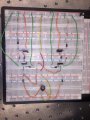
I am trying to implement ona breadboard an electric circuit, as the one in the figure. The first capacitor on the left is not important. I tried to create it on a breadboard (it was my first time) but for some reason it is not working. I try to attach some image to explain how I hook everything up. Could you please make me notice where my mistake is? The input comes from a piezoelectric element, and the breaker should open the circuit and let the current flow through the inductor. It seems fine to me, but if i measure the voltage on the load, I have no output.


I am trying to implement ona breadboard an electric circuit, as the one in the figure. The first capacitor on the left is not important. I tried to create it on a breadboard (it was my first time) but for some reason it is not working. I try to attach some image to explain how I hook everything up. Could you please make me notice where my mistake is? The input comes from a piezoelectric element, and the breaker should open the circuit and let the current flow through the inductor. It seems fine to me, but if i measure the voltage on the load, I have no output.
Attachments
-
 334.8 KB Views: 18


