Choosing the correct LED driver IC

Thread Starter

Track99

Joined Jun 30, 2022
81
Hi all.

So this post is basically a post where I need ur feedback to tell me if I made the right choice of an LED driver IC.


I purchased a RGBW led. I would like to control the brightness and color of this LED at its max voltage and current values; within an Arduino.

After a lot of digging around I came to the conclusion that the LM3464 is my best option. ( https://www.ti.com/product/LM3464 )

I would appreciate it if someone could tell me if I chose a 'good enough' driver IC based on the info I am giving you below.

The datasheet for the led is at https://www.ledsupply.com/content/pdf/XLampXML_Color.pdf

Below are the main characteristics of the led.

1715728024565.png

Here are my requirements:

1) I need to be able to control the brightness of each LED, with an Arduino; up to its full brightness! ( I feel this is possible cause this driver is rated for a max Vout of 80V and 4 Amps. )

2) I need to be able to control all 4 colors with an Arduino. ( I feel this is possible since this IC has 4 channels. )

It believe, that the LM3464 LED driver IC can output up to 80V and 4A per channel, which is sufficient to meet the forward voltage and current requirements of my RGBW LED. This allows me to drive each LED color at its maximum specified current.

The LM3464 has 4 channels, enabling individual control of each LED color using PWM signals from an Arduino. This means that I can adjust the brightness of each color independently.

I believe I need to dig up the proper current-limiting resistors which gotta go in series with each LED to limit the current to stop them from overdriving.

Can someone tell me if my choice of a driver will work out for me? Can someone tell me if I am making any major errors in my conclusions?

Ty!
 
Last edited:

BobTPH

Joined Jun 5, 2013
9,342
You don’t need the driver. If you are controlling brightness with PWM and current with a resistor, all you need is a MOSFET for each color.
 

ElectricSpidey

Joined Dec 2, 2017
2,900
If you made the right choice...that depends on a lot of things.

Sure, that driver chip will do the job, but it's kinda like blowing up a dinghy with a battleship.

Are you sure you need all of those bells and whistles to drive a single RGBW LED?

Do you plan to use the power supply example given?

Do you understand that chip works by keeping the MOSFETs in their linear zone? (meaning you will need heatsinks on them)

You mention "current limiting resistors" this driver doesn't use current limiting resistors, it does instead have "sense" resistors that have to be chosen according to the presented formula. (the MOSFETs do the voltage dropping and current limiting)

It personally wouldn't be my choice to drive a single RGBW LED, but that's just me, I would probably just go with 4 TC4420/29 gate drivers and do my thermal management with the proper heatsink. (yes, those gate drivers can also directly drive LEDs) Of course if you are actually running many of those LEDs in series than maybe I would choose a proper LED driver...but probably not that one.
 

ElectricSpidey

Joined Dec 2, 2017
2,900
Something I just noticed about this driver...the dimming function seems to be universal, if that is the case you will not be able to create the secondary colors such as Yellow, Cyan, Majenta...etc.

Correction:

If you were to use that driver you would need high side switches to determine which channels are in use.

Then you could produce dimmable Red, Green, Blue, White, Yellow, Cyan and Majenta but not colors like Orange.

And you would not be able to fine tune the secondary colors.
 
Last edited:

BobTPH

Joined Jun 5, 2013
9,342
Are you really trying to control a single LED with that driver chip? That chip is designed to control many LEDs in series. What voltage are you using to power the LED?
 

dovo

Joined Dec 12, 2019
72
If I understand the datasheet correctly the LM3464 does not allow independent current control on the fly. All four channels pulse together controlled by a signal on pin 2. You need to control each LED over its full current range and this part will not do that.

As BobTPH says, four MOSFETs with current limiting resistors can work. The difference between this and the LM3464 constant current drivers is that the LED luminosity has a new temperature-dependent term because LED current and luminosity will tend to rise as the LEDs warm up. The LEDs already are temperature dependent as shown below with luminosity decreasing as the LEDs warm up. I think I can calculate this but in any case the resistor circuit seems to offer a better temperature coefficient of luminosity.

I will post a circuit consisting of 4 x MOSFETs and 4 x resistors with some MOSFET part numbers.

1715835043534.png


1715834225762.png

1715834538804.png

LM3464 Datasheet https://www.ti.com/lit/ds/symlink/lm3464.pdf?ts=1715818203742

Cree Datasheet https://www.ledsupply.com/content/pdf/XLampXML_Color.pdf


1715830933466.png
 

dovo

Joined Dec 12, 2019
72
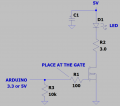
Using a logic level MOSFET this circuit can be driven directly off a 3.3V Arduino driver pin. The LED current-limiting resistor value (and LED current) depends on the maximum illumination the product requires. The lower the pulsed current is the higher the duty cycle is and the lower the RMS current is. It is the RMS current that drives the current-limiting resistor power dissipation. To keep power consumption and resistor power dissipation down more resistance is better.

Let's calculate a reasonable value for each LED resistor, Red, Green, Blue, White to pulse at or below the LED spec max of 1A and for a die temp of 150 deg C. As the die heats up the LED forward voltage decreases.

Red: 2.25V - (125 °C x 1.8 mV/°C) = 2.03V
Green: 3.3V - (125 °C x 4.0 mV/°C) = 2.80V
Blue, White: 3.1 - (125 °C x 3.0 mV/ °C) = 2.73V

Referring to the BSS806NE MOSFET datasheet let's call Rds ON = 50 milliohms and at 1A the MOSFET S-D voltage is 50 mV. Vdd is the LED supply voltage.

Red: R = (Vdd - 2.03V - 50mV)/1A. For Vdd = 5.00V, R = 2.92 ohms
Green: R = (Vdd - 2.80V - 50mV)/1A. For Vdd = 5.00V, R = 2.15 ohms
Blue, White: R = (Vdd - 2.73V - 50mV)/1A. For Vdd = 5.00V, R = 2.22 ohms

A one size fits all resistor value must be at least 2.92 ohms so that the Red LED current never exceeds 1 amp. With a 3 ohm resistor, and a duty cycle of 35% for 350 mA average current, the RMS current is 0.59 A. The 3 watt resistor then dissipates 1.0 watt. The 10k pulldown ensures the MOSFET is OFF when the Arduino is powered OFF. The 100 ohm gate resistor helps keep the MOSFET from breaking into an HF oscillation.

Decoupling capacitor carries up to 4 x 0.59A = 2.4 amps of ripple current when the four LEDs pulse in phase and so the cap should be selected accordingly. I will check this all tomorrow morning for errors of thought and math.

LED datasheet
1715844040578.png

1715843318746.png

A simple LED driver
1715846316220.png


SOT23-3 package MOSFETs, price $0.14 each for 100
BSS806NH6327XTSA1
https://www.infineon.com/dgdl/BSS80...c1f67&fileId=db3a304330f686060131185f0553451c

BSS806NEH6327XTSA1
https://www.infineon.com/dgdl/Infin...n.pdf?fileId=db3a304340f610c201410d1548de3366

LED https://www.ledsupply.com/content/pdf/XLampXML_Color.pdf
 

Ya’akov

Joined Jan 27, 2019
9,277
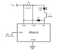
If you would like to use a simple driver chip, you might consider the CN7511. It is a 1.5A 2.8-6V constant current driver with a chip enable pin that can be used for PWM operation. You can get them for ~$0.60/ea (including shipping if you buy 10) from here, for example.
 

Thread Starter

Track99

Joined Jun 30, 2022
81
Are you really trying to control a single LED with that driver chip? That chip is designed to control many LEDs in series. What voltage are you using to power the LED?
This is an RGBW LED. It has 4 LEDs packed into one housing. Each LED has its own input power terminals. That's why I chose this driver chip. Ty
 

BobTPH

Joined Jun 5, 2013
9,342
This is an RGBW LED. It has 4 LEDs packed into one housing. Each LED has its own input power terminals. That's why I chose this driver chip. Ty
As I said, that chip is designed to use a high voltage (up to 80V) to drive up to 30 LEDs in series. Using it at 2 to 3V to drive a single LED on each channel is severe overkill. Also the heat management will be more difficult using this chip than using 4 separate resistors.

You came to ask if you were using the right driver and the consensus is clearly no.
 

dovo

Joined Dec 12, 2019
72
If you would like to use a simple driver chip, you might consider the CN7511. It is a 1.5A 2.8-6V constant current driver with a chip enable pin that can be used for PWM operation. You can get them for ~$0.60/ea (including shipping if you buy 10) from here, for example.
Thank you for bringing this useful IC to our attention. For an application dissipating a watt the PCB Design Considerations on datasheet page 7 should be observed. I can run thermal calculations to determine a minimum thermal pad size but offhand I'm thinking a square of copper 20 mm x 20 mm will suffice.

CN7511 datasheet https://www.makerguides.com/wp-content/uploads/2024/04/CN5711-datasheet.pdf
 

Thread Starter

Track99

Joined Jun 30, 2022
81
Using a logic level MOSFET this circuit can be driven directly off a 3.3V Arduino driver pin. The LED current-limiting resistor value (and LED current) depends on the maximum illumination the product requires. The lower the pulsed current is the higher the duty cycle is and the lower the RMS current is. It is the RMS current that drives the current-limiting resistor power dissipation. To keep power consumption and resistor power dissipation down more resistance is better.

Let's calculate a reasonable value for each LED resistor, Red, Green, Blue, White to pulse at or below the LED spec max of 1A and for a die temp of 150 deg C. As the die heats up the LED forward voltage decreases.

Red: 2.25V - (125 °C x 1.8 mV/°C) = 2.03V
Green: 3.3V - (125 °C x 4.0 mV/°C) = 2.80V
Blue, White: 3.1 - (125 °C x 3.0 mV/ °C) = 2.73V

Referring to the BSS806NE MOSFET datasheet let's call Rds ON = 50 milliohms and at 1A the MOSFET S-D voltage is 50 mV. Vdd is the LED supply voltage.

Red: R = (Vdd - 2.03V - 50mV)/1A. For Vdd = 5.00V, R = 2.92 ohms
Green: R = (Vdd - 2.80V - 50mV)/1A. For Vdd = 5.00V, R = 2.15 ohms
Blue, White: R = (Vdd - 2.73V - 50mV)/1A. For Vdd = 5.00V, R = 2.22 ohms

A one size fits all resistor value must be at least 2.92 ohms so that the Red LED current never exceeds 1 amp. With a 3 ohm resistor, and a duty cycle of 35% for 350 mA average current, the RMS current is 0.59 A. The 3 watt resistor then dissipates 1.0 watt. The 10k pulldown ensures the MOSFET is OFF when the Arduino is powered OFF. The 100 ohm gate resistor helps keep the MOSFET from breaking into an HF oscillation.

Decoupling capacitor carries up to 4 x 0.59A = 2.4 amps of ripple current when the four LEDs pulse in phase and so the cap should be selected accordingly. I will check this all tomorrow morning for errors of thought and math.

LED datasheet
View attachment 322439

View attachment 322437

A simple LED driver
View attachment 322441


SOT23-3 package MOSFETs, price $0.14 each for 100
BSS806NH6327XTSA1
https://www.infineon.com/dgdl/BSS80...c1f67&fileId=db3a304330f686060131185f0553451c

BSS806NEH6327XTSA1
https://www.infineon.com/dgdl/Infin...n.pdf?fileId=db3a304340f610c201410d1548de3366

LED https://www.ledsupply.com/content/pdf/XLampXML_Color.pdf
Ty very much. How do you calculate C1?
 

Thread Starter

Track99

Joined Jun 30, 2022
81
As I said, that chip is designed to use a high voltage (up to 80V) to drive up to 30 LEDs in series. Using it at 2 to 3V to drive a single LED on each channel is severe overkill. Also the heat management will be more difficult using this chip than using 4 separate resistors.

You came to ask if you were using the right driver and the consensus is clearly no.
I guess this is what the forum is telling me. Lol.

gregf.JPG
 

Thread Starter

Track99

Joined Jun 30, 2022
81
If you would like to use a simple driver chip, you might consider the CN7511. It is a 1.5A 2.8-6V constant current driver with a chip enable pin that can be used for PWM operation. You can get them for ~$0.60/ea (including shipping if you buy 10) from here, for example.
Ty. I am unable to find that IC on any US sites. Do u know of an equivalent US model ? Ty
 

dovo

Joined Dec 12, 2019
72
Ty very much. How do you calculate C1?
To select the C1 we need some more information; Supply voltage, switching frequency and operating temperature. I will go through an example using 5 V, 1000 Hz and 85 deg C or greater. I chose 1000 Hz to reduce the size of the capacitor. I don't know if this is a good frequency for your Arduino. Frequency is flexible in that to have no flicker we want to pulse the LEDs at a 100 Hz or faster rate but not so fast that we run up against Arduino limitations. I chose 0.25 V as the voltage sag of the cap during a 350 us pulse just because 5% sag sounds okay to me.

Capacitance: How far the capacitor discharges as 4 amps is drawn for ~35% of the 1000 us period.
i = C dv/dt
C = i/(dv/dt) = 4A/(0.25V/350us) = 5600 uF

Specs we can use to search at Digikey or Mouser
V = 6.3V or greater
C = 5600 uF or greater
RMS current: >1.4A
Temperature range 0 to <85 deg. C or hotter
Lifetime? I like to use 5000 hour at 105 deg. C or longer but your application might be fine with a shorted life part
Case? For now I will use Through Hole & Radial

Searching with these parameters and clicking Price for this cap from a reputable company.

Chemi-con 565-EKYC160ELL562MK30S-ND
Datasheet https://www.chemi-con.co.jp/products/relatedfiles/capacitor/catalog/KYCLL-e.PDF
Price $1.00 in single quantities

V= 16V
C = 5600 uF
Temp -40 to +105 deg C
Endurance (lifetime) 5000 hrs at 105 deg C at rated ripple current
RMS current = 3.12A @ 100 kHz, 2.652A @ 120 Hz.

This is what I'd call a long life capacitor. Cap life at any temp can be calculated by doubling the life for every 10 deg C decrease. For example, operate it at 45 deg C and life is 64X longer which is 320k hours which is 37 years. End of life is defined as a change of 25% in capacitance and/or a 2X increase in D.F. (Dissipation Factor). This is 2X for ESR. That is one reason it's good to derate the ripple current so that as a cap ages and its ESR rises it doesn't go into a self-heating death spiral.
 

Thread Starter

Track99

Joined Jun 30, 2022
81
Top