Choosing MOSFET replacement, Thrustmaster TX PC steering wheel

Thread Starter

ozzy1202

Joined Apr 30, 2020
3
Hello!
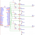
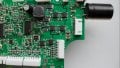
I have a broken Thrustmaster TX steering wheel, DRV8301 BLDC motor driver burned out as in the pictures below. There are 6 NTMS5835NL MOSFETs, they don't look burned out, but I suspect they could be broken as something caused the driver to burn out. The common thing in this steering wheels is that the magnet detaches from the rotor (it is glued and the glue lets go at some point) in the B4260M-003 motor and it causes MOSFETs and DRV8301 to burn, but I checked it and the magnet is not loose in this case, so that was not the reason why the DRV8301 burned I believe. I do want to replace DRV8301 and MOSFETs to see if it will work then, but as far as I can see these NTMS5835NL MOSFETs are obsolete right now and I can't find them anywhere to buy. I need to find another MOSFETs that could be used instead, but I am not really sure which paramters are the most important in this case. I found AO4268 MOSFET which has the same package and pinout and seems to have most parameters similar or better than the original MOSFETs, could it be used as a replacement here or not really? If not, which paramteres are the most important in this application?
 

Attachments

ci139

Joined Jul 11, 2016
1,898
your first step could be searching the net for similar failures for the device - to get the list of opinions for the possible causes
 

Thread Starter

ozzy1202

Joined Apr 30, 2020
3
As I already said in my first post, the failures described on the internet related to motor driver and MOSFETs are because of the rotor magnet in the motor getting loose, which is not the case in this particular example as far as I can tell. I disassembled the motor and the magnet sits still, I can't move it by hand while holding the shaft by pliers. Before I will put it back together, I will add some new, better glue to this magnet to prevent it from getting loose in the future even though it is OK now. There are no failure cases documented on the internet related to this part of the board that were caused by something else, it was always an issue with the rotor magnet.
I kind of suspect that possibly one of the MOSFETs failed by itself, maybe because of some manufacturing defect or something and it caused the failure of the driver. I kind of hope it will work when I will replace the DRV8301 and MOSFETs, but I wouldn't be sure untill I try this. As I said in my first post, the thing is I don't know what MOSFETs to use, as the original ones are not available to buy anywhere. So that is what I would like to know. Here is a datasheet of the original NTMS5835NL MOSFET: https://www.onsemi.com/pub/Collateral/NTMS5835NL-D.PDF and here is a datasheet of the AO4268 MOSFET that I found that I would like to use instead of the original ones: http://www.aosmd.com/res/data_sheets/AO4268.pdf Would these MOSFETs be OK for that board? If not, what parameters of the MOSFETs I should look for to choose something fitting?
I also tracked the circuit a little bit and draw small schematic. It seems as this part of the board is connected as in the schema in the attachement. The burned part is next to the pins 34 (SL-C), 35 (GL-C), 36 (SH-C), 37 (GH-C) and it seems like pin 34 (SL-C) was the one affected the most.
 

Attachments

ci139

Joined Jul 11, 2016
1,898
there is slight difference in avalanche current old/new 37/30A , minor difference in gate charge (Fig.8)/(Fig.7) and yet larger difference in SWITCHING CHARACTERISTICS / PARAMETERS the td.ON t.RISE td.OFF t.FALL (ns) 15 45 22 9 / 7.5 6.5 38 8 ??? - it's not much though but depending on your timings it may result in both shoulders open when the new MOSFET opens faster and closes slower ???
 

Thread Starter

ozzy1202

Joined Apr 30, 2020
3
I went through quite a bit of datasheet of MOSFETs in this package and possibly I could find something with times that are closer to the original to be on a safer side, but most of the MOSFETs in this package have way lower avalanche current. I couldn't find anything that has maximum avalanche current as high as 37A, and 30A is actually very rare, most are somewhere around 7A-15A range from what I have seen. How important is this paramter in this application? Also avalanche energy seems to differ a lot between different MOSFETs in this package, how important is avalanche energy in this case?
 

ci139

Joined Jul 11, 2016
1,898
i know random something about the mosfets ... but i don't know much about the motor drivers

assuming the switching of the mosfet causes current to ramp linearily on a motor coil . . . we might assume the avalanche current ? is not so crucial ?
(gradually waking up) incase of the PWM -- the current likely ramps to above average output at given time ... so it might be crucial for efficiency (mosfet op.-g temperature)
. . . on the other hand ? it likely contributes or has a relation on opening speed of the mosfet ? -- e.g. how much power dissipates on the linear region . . . maybe , sorry i must confirm the previous hypothesis

the common/average switching timing parameters are likely the speed limit of the mosfet ← to gain these assumes the sufficient and proper driving the particular mosfet . . . is application dependent . . . as i said -- i donno much about the motor driving

usually the bridge drivers have some sort of mechanism implemented to ensure the "safe switching" / that the both shoulders wont get open simultaneously -- about digging to the driver chip data . . . i will do that on request not voluntarily (because it's working through the entire datasheet and more . . . if they assume reader being familiar with such devices)
 
Last edited:

ci139

Joined Jul 11, 2016
1,898
the d/s http://www.ti.com/lit/ds/symlink/drv8301.pdf?ts=1588355645064 hints lot of nets requiring careful PCB design
  1. the current sensing (i yet can't tell if it's anyhow implemented on your circuit)
    ON the d/s the GH/L_A driver node shows no ((limiting/))sensing resistor ?
    ... 7.3.1 "The peak gate drive current and internal dead times are adjustable to accommodate a variety of external MOSFETs and applications." ... (likely allows flexible choice of MOSFETs but such requires adjusting it - trivial ? but you asked about your MOSFETs)
  2. "The buck converter can provideup to 1.5 A to support MCU or additional system power needs." the input path to iC must support that "power" (+sufficient cooling for)
  3. "The SPI ..." -- noiseless comm (← i yet not reached the role of that interface --e.g.-- how and when it's used)
  4. 7.3.4.1 "To protect the power stage from damage due to excessive currents, VDS sensing circuitry is implemented in the DRV8301.Based on the R.DS(on) of the external MOSFETs ..." -- the R.DS.ON depends also on device temperature (, the value of the Id) . . . ??? Figure.4 , Figure.5
  5. ...
a bit photoshopped if anyone can read out something from here - SL_C is a weird pin to fail unless the excessive overcurrent from motor coil ? forcing it below the "Vss" ... can't be the case coz 10mΩ . . . d/s has 10Ω gate current limitting resistors this one has 1Ω , NTMS5835NL R.G = 1.2Ω Ciss = 2115pF Crss = 220pF (Pg.9) ← my last guess likely wont hold also (extra charge accumulating at gate causing the excessive drive current) . . . might be ? static charge on driver board ? i donnoZoom1.jpg
_____________________________
about IAS :: ((my IAS ~ tr hypothesis takes stat. run through the several d/s)) . . . found some detailed links (according to what the higher IAS may hint the lower chance of failure)
https://www.infineon.com/dgdl/an-1005.pdf?fileId=5546d462533600a401535590ab660f3a
https://www.st.com/resource/en/appl...cteristics-and-ratings-stmicroelectronics.pdf
 
Last edited:
Top