***Choice of op-amp for butterworth filter***

Thread Starter

artmaster547

Joined Jan 6, 2016
409
Hi All
I'm trying to design a low pass butterworth filter, which I wish to add a stage to follow a differential amplifier and there will be four of these connected stages on one PCB, I have come up with a design using a Texas Instruments TL071 amplifier however I feel like this is a little accessive and I will then require multiple physical opamp packages (x4). Whereas with my differenital amplifier stage there were 4 opamps in one package, would it be suitable to also use this same opamp for the butterworth filter that would be STMICROELECTRONICS MC3317D Op Amp Quad, I'm just thinking about trying to save on board estate.

Kind Regards
Jonathan Sundaram
 

Papabravo

Joined Feb 24, 2006
22,115
I don't clearly understand your problem. You can get the same opamp in singles, duals and quads. Look for TL071, TL072, TL074. What are the specifications of the Butterworth filter?
 

Thread Starter

artmaster547

Joined Jan 6, 2016
409
I don't clearly understand your problem. You can get the same opamp in singles, duals and quads. Look for TL071, TL072, TL074. What are the specifications of the Butterworth filter?
oh wait is for example tl074 a quad? The spec for it is cutoff of 1kHz and gain of 1 V/V
 

Thread Starter

artmaster547

Joined Jan 6, 2016
409
Unless there is something else you haven't mentioned, you should be fine. Don't forget the decoupling caps on the PCB.
By decoupling do you mean the capacitors that I already had in the design or do I need to include more sorry if these questions are super stupid I'm a beginner and want to learn as much as possible
 

Papabravo

Joined Feb 24, 2006
22,115
By decoupling do you mean the capacitors that I already had in the design or do I need to include more sorry if these questions are super stupid I'm a beginner and want to learn as much as possible
Yes those capacitors on the power supply rails. I'm not a mind reader -- how would I know you had them since you did not provide a schematic. They are often overlooked in first designs.
 

Thread Starter

artmaster547

Joined Jan 6, 2016
409
Yes those capacitors. I'm not a mind reader -- how would I know you had them since you did not provide a schematic. They are often overlooked in first designs.
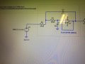
I apologise the following is a photo of the circuit, I was simulating it first just make sure I was getting the correct waveforms:
 

Attachments

Papabravo

Joined Feb 24, 2006
22,115
oh wait I have done that in the actual eagle schematic sorry, I understand what you meant now, so a decoupling in between the positive and negative supply right?
Not quite. Decoupling should provide a low impedance path to GND for each supply. It is usually done with multiple capacitors in parallel for each supply.
 

Thread Starter

artmaster547

Joined Jan 6, 2016
409
Not quite. Decoupling should provide a low impedance path to GND for each supply. It is usually done with multiple capacitors in parallel for each supply.
Hmm ok I've never seen that done before I will definitely try this out then, I'm modifying a design that was given to me by an experienced engineer I'm surprised that they didn't implement this feature with their op-amps. Would you mind drawing up a schematic quickly just to ensure I do this correctly thanks J
 
Top