Chinese DIY 0-30V 0.2-3A Power Supply Troubleshooting

Audioguru again

Joined Oct 21, 2019
6,826
You have a Chinese copy of a kit made in Greece 16 to 20 years ago. It was a project at Electronics-Lab.com and it had MANY problems. I fixed it by making MANY changes.
Basically, its transformer voltage was too low for it to produce 30VDC at 3A but the TL081 opamps used were operating at a total supply voltage that is higher than their maximum allowed voltage, so the opamps fail soon. Also many of its parts are overloaded and burn up.
For the parts you have, if you use a 20VAC transformer and a huge heatsink for the output transistor then it can produce a maximum of 20VDC at 1.5A.
 

Irving

Joined Jan 30, 2016
5,195
hi I,
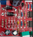
The PCB image silkscreen shows 5V1.?
E
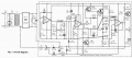
Your right, and in 2 places (D8 too) but the schematic shows 1N752, a 5.6v part (The device family starts at 1N746 = 3.3v etc.) And the 'troubleshooting' guide says measure -5.6v..

<mild rant on>
I hate PCBs with no references to the schematic, makes it so much harder to follow. And no BOM in the text... Spare us from 'hobbyists'...
<mild rant off>
 

Irving

Joined Jan 30, 2016
5,195
one strange thing is at the positive of the capacitor down left but on the right side, im measuring 0 Volts, i have already changed the capacitor but nothing changed.
The positive side is the input of the zener 5V1
Not strange at all, if you're referring to C3, because the capacitor's plus side is connected to ground as is the anode of the zener diode. Those are part of a negative supply rail. All voltages across D7, C3, etc are negative w.r.t. ground. The cathode of D7 (the end without the black bar) and the - side of C3 should be -5.6v relative to ground.

Changing parts randomly without understanding their purpose isn't going to help.

Read the section on V- supply on page 5 of the 'manual'...

Here are some voltages to check, black probe on GND. They are AC or -ve DC.

voltages.png
 

Irving

Joined Jan 30, 2016
5,195
You have a Chinese copy of a kit made in Greece 16 to 20 years ago. It was a project at Electronics-Lab.com and it had MANY problems. I fixed it by making MANY changes.
Basically, its transformer voltage was too low for it to produce 30VDC at 3A but the TL081 opamps used were operating at a total supply voltage that is higher than their maximum allowed voltage, so the opamps fail soon. Also many of its parts are overloaded and burn up.
For the parts you have, if you use a 20VAC transformer and a huge heatsink for the output transistor then it can produce a maximum of 20VDC at 1.5A.
Hi AG A

Is that personal or anecdotal experience?

Either way, easy to fix. Its true, the early TL081 were 30v parts, but most are now 36v, though still 30v CM. Anyway, replace with TLE2071 which are pin-compatible 38v parts with rail-to-rail CM and better all round on noise, GBW, offset, etc.

The output transistor on a big linear supply is always going to be an issue. The suggested device for Q4 is a 40W 6A beast. At 3A and near zero output volts its going to be dissipating the best part of 33v * 3A = 99W so its well underspec'd. There isn't a single device that's going to handle that - a BU323Z on a 0.4degC/W heatsink gets close, a pair of them, each on a 75mm long ABL153 heatsink with a 60mm fan would do it and would be a relatively easy modification, though thats nearly $50 of heatsink & fan.

There's nothing else I can see with a quick scan that looks unduly stressed.
 

Audioguru again

Joined Oct 21, 2019
6,826
My fix used two 2N3055 output transistors to share the heat, a 28VAC/4.3A transformer, a 12000uF much larger main filter capacitor and TLE2141 opamps that have a maximum allowed supply of 44V. I changed the negative supply to -1.4V. The old TL081 opamps have the Phase Inversion problem and therefore needed the much higher negative supply voltage.
 
You have a Chinese copy of a kit made in Greece 16 to 20 years ago. [...]
It goes back to 1978, almost 42 years ago.

OP your problem might be that many of these kits came with the wrong current-sense resistor and the current-limit mode gets stuck on.
Should be 5W 0.47R, but is 47R !
 

Attachments

Last edited:

Irving

Joined Jan 30, 2016
5,195
It goes back to 1978, almost 42 years ago.

OP your problem might be that many of these kits came with the wrong current-sense resistor and the current-limit mode gets stuck on.
Should be 5W 0.47R, but is 47R !
You can see from the picture the OP posted in #4 it's 0R47

The wrong value there wouldn't explain the missing -5v rail.
 

Irving

Joined Jan 30, 2016
5,195
My fix used two 2N3055 output transistors to share the heat, a 28VAC/4.3A transformer, a 12000uF much larger main filter capacitor and TLE2141 opamps that have a maximum allowed supply of 44V. I changed the negative supply to -1.4V. The old TL081 opamps have the Phase Inversion problem and therefore needed the much higher negative supply voltage.
Even a pair of the venerable 2N3055 (a highly prized find on old equipment scavaging in my youth) is very marginal here even on a <1degC/W heatsink, and it's hfe is so low the driver bjt will have problems at higher output currents.
 
Last edited:
You can see from the picture the OP posted in #4 it's 0R47
The wrong value there wouldn't explain the missing -5v rail.
Sorry I thought it was a stock photo of the board.
Without the -5.1V rail, Q1 will stay on shorting U2's output and it will get hot- there should be no output voltage possible but OP got 20V... which is another problem. R14 1k5 looks pulled in the pic?

You need voltage readings on each IC pin to see if the rail is overloaded verses not working. Zeners usually look much different with a bigger stripe and thicker body, on the kits of this PSU I have.
 
Top