chebyshev filter design for vhf fail. Why?

Thread Starter

cmrincon

Joined Oct 25, 2017
40
Hi, noob here.:D
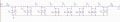
This weekend i have been designing a VHF filter and trying to characterize real components to get the best simulation of the real filter. I Will make the circuit with smd parts 0805 or 0603.

I supose that i did a bad job as i get -2dB max in the bandpass and less BW than expected.

My target BW is from 115 MHz to 150 MHz and get -1dB min in the bandpass. How can i archieve that? It is posible to get -1dB in the passband using chebyshev pass band filter?
i attach images of circuits and graphs. If you ask me i can simulate the circuit on ltspice and upload it or give you the component list.
Thanks you in advance
 

Attachments

danadak

Joined Mar 10, 2018
4,057
For sure lumped element filters in VHF are on the edge in terms of accounting
for complete and accurate models of PCB and elements.

Did you hand crank out computed values or use a VHF sim ?

Funny thing is we normally experience too much BW due to losses,
not the other way around. But your passband did show there are
loss elements present.

Noob here also.


Regards, Dana.
 

BR-549

Joined Sep 22, 2013
4,928
May I ask what is the overall picture is. Source and purpose of input signal.

How would you described frequency flow thru the real image circuit?

Are you trouble shooting a simulation.....or have you swept the circuit?
 

Thread Starter

cmrincon

Joined Oct 25, 2017
40
May I ask what is the overall picture is. Source and purpose of input signal.

How would you described frequency flow thru the real image circuit?

Are you trouble shooting a simulation.....or have you swept the circuit?
Hi! The purpose of the circuit is be part of a communication system. I would like to use it to archive a better signal reception in my sdr. I need a good rejection of the FM band 88-108 MHz and good reception of the 3 m band (144 MHz). My secundary goal (optional) is be posible of receive the airband, which is next to the fm band.

My first problem is i don't know if i can expect less thaan 2 dB attenuation in the passband. I would like to reduce it as much as posible.
My second problem is that i don't know the limits of chebyshev filters: i don't know if i am tackling the problem correctly or if a must use another tipe of filter in order to archieve the required caracteristics ( Should i use an active filter? or LNA + passive filter?).
Thanks you
Cesar
 

BR-549

Joined Sep 22, 2013
4,928
What a bummer. I'm sure that transmitter is not alone either.

Well, the only thing good about it is, you can compare demodulation techniques. From what I've read, the SDR was made for these situations.

Do you suspect that the SDR is being overloaded?

Have you compared the SDR results with conventional receivers?

Edit: You might try to permanently co-phase two verticals at your house, and aim the null towards the large antenna structure.
 
Last edited:

Thread Starter

cmrincon

Joined Oct 25, 2017
40
What a bummer. I'm sure that transmitter is not alone either.

Well, the only thing good about it is, you can compare demodulation techniques. From what I've read, the SDR was made for these situations.

Do you suspect that the SDR is being overloaded?

Have you compared the SDR results with conventional receivers?
I have no more recivers to make a comparation but i can say that my sdr are overloaded as i can hear some fm stations far away from the fm band
 

Thread Starter

cmrincon

Joined Oct 25, 2017
40
Have you got any equipment?
100 mhz oscilloscope, and i can use any sdr usb dongle as a low cost spectrum analyzer. Though i can use my college equipment(spectrum analyzer, network analyzer, signal generators, wide band oscilloscopes, and so on). I must say that my college equipment is great.
 

BR-549

Joined Sep 22, 2013
4,928
With your predicament, I think I would try a simple bandpass to ground first. Have you got an adjustable low value capacitance cap? You could series it with a coil......and shunt FM to ground right at antenna input. One can also tune by collapsing and expanding the coil.

If further adjustment is needed.....such as the Q or move it up or down a little......one can sweep the input and get a visual indication. Check generator for constant sweep amplitude with scope.

I like filters. But half of blocking something....is giving it an easy place to go.

I have no overload problems here, but I have a directional wide noise source that at times, drives me nuts.

Antenna orientation was the best solution.
 

Thread Starter

cmrincon

Joined Oct 25, 2017
40
With your predicament, I think I would try a simple bandpass to ground first. Have you got an adjustable low value capacitance cap? You could series it with a coil......and shunt FM to ground right at antenna input. One can also tune by collapsing and expanding the coil.

If further adjustment is needed.....such as the Q or move it up or down a little......one can sweep the input and get a visual indication. Check generator for constant sweep amplitude with scope.

I like filters. But half of blocking something....is giving it an easy place to go.

I have no overload problems here, but I have a directional wide noise source that at times, drives me nuts.

Antenna orientation was the best solution.
Thanks you. It may work.
I have been looking for more solutions and i found this:
https://www.rtl-sdr.com/rtl-sdr-com-broadcast-fm-band-stop-filter-88-108-mhz-reject-now-for-sale/
Its more expensive than a simple coil and a adjustable capacitor but i think is worthy.
 
Top