Chage phase of a square wave

Thread Starter

wildarms

Joined Aug 2, 2013
6
It's funny since that is what i´ve been telling myself for a while now, i used to use pics a good while ago, but i doubt we can use it for this (and i dont really have the money or time to get one now).

But, i just wanted to clarify, yeah, this obviously wont be a perfect mux (or perfect square signals, since they will be the ones sampling), but at least, i wanted to make it so it can recover the signal -well enough- in the other side, I'm not sending complicated signals, is just a 1 tone signal (a sine), so is 3, 1 tone signals at different frequencies each one (making 3 "messages").

I thought that while not perfect, even with a 555 it might do the trick, or with the logic gates even better, at least for when it comes to reconstruct the waves to a point where they look like sine waves (even if all ugly, but you might still be able to say its a sine wave).
 

WBahn

Joined Mar 31, 2012
33,021
Also, i can't seem to find where to edit the thread, just realized that i wrote "chage" instead of "change"
Only a moderator can change the thread title.

If you use the warning-sign looking button at the top-right of every post, you can report a post to a moderator. I would recommend reporting the first post in the thread and asking them if they can change the thread title to something else. Be sure to include the entire thread title you want to use on a line by itself so that they can do a simply copy/paste operation.
 

THE_RB

Joined Feb 11, 2008
5,438
What about another 4017 counter solution?

You could set the 4017 to repeat a sequence of 6. Then use 3 diodes for each phase, so each phase gets to be on for 50% of the 6 steps.

Total 1 IC and 9 diodes. (May also need 3 pulldown resistors).

Rich (BB code):
sequence
123456
111
  222
3   33
(where the numbers are the locations of the 3 diodes for each phase)
 

WBahn

Joined Mar 31, 2012
33,021
I'm not visualizing what is happening here.

How are you going to use these nine diodes to multiplex three signals together?
 

THE_RB

Joined Feb 11, 2008
5,438
Sorry WBahn my description was lazy and not clear.

The 4017 is configured with 6 sequential output pins (like a light chaser).

The pins are numbered;
123456

diodes go from 3 pins to the output, so these are 3 diodes from pins 123 to output 1;
123456 (the 4017 output pins)
111 (3 diodes, 3 anodes to 4017, the cathodes joined become output 1)

so;
Rich (BB code):
123456  (6 pins of 4017)
111     (3 diodes to output 1)
  222   (3 diodes to output 2)
3   33  (3 diodes to output 3)
So each output is HI (diodes conducting) for 50% of the time (3 pins out of 6 total).

And the phase difference is 120 degrees between each output. It's basically a hardware form of a 6-step sequence which is often used in software to make 3 phases with 50% duty.
 

WBahn

Joined Mar 31, 2012
33,021
Okay, but how does that address what the OP is trying to do, which is to multiplex three signals together? It would seem that you don't WANT a 50% duty cycle because then your three signals have significant overlap. Why not just use three outputs (assuming the 4017 can be configured that way) or tie the six them together in disjoint pairs in order to get three non-overlapping signals each with a 33% duty cycle?

I think the OP asked for something not realizing that it was inconsistent with what he needs.
 

BillB3857

Joined Feb 28, 2009
2,573
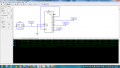
What about something like this, using a 4017? It would require a clock 9X the required output rather than 6X. Also, if the pulse width out of a single count is not enough, a simple OR function of 0-1, 3-4, 6-7 would double the pulse width and still leave a null between positions.
 

Attachments

THE_RB

Joined Feb 11, 2008
5,438
Okay, but how does that address what the OP is trying to do, which is to multiplex three signals together? It would seem that you don't WANT a 50% duty cycle because then your three signals have significant overlap. Why not just use three outputs (assuming the 4017 can be configured that way) or tie the six them together in disjoint pairs in order to get three non-overlapping signals each with a 33% duty cycle?

I think the OP asked for something not realizing that it was inconsistent with what he needs.
Maybe I misread what he was asking?

He said this; "First things first, let me explain my objective, i am doing this in order to do a multiplexer, i'm going to to have 3 different waves that im going to need to take samples of, and put them all together, so, in order to do the sampling, i need the 3 square wave signals with 3 phases ...
... and i will be generating the square wave directly from a wave generator, so i pretty much just have to do 2 circuits to change it to 120° and other to 240° since the 0° is just the original one."


Which I assumed meant he wanted to generate a 3 phase squarewave signal which he could then use in testing?
 

WBahn

Joined Mar 31, 2012
33,021
He says, "in order to do the sampling, i need the 3 square wave signals with 3 phases ...". These square waves are NOT, as I read it, the "3 different waves that im going to need to take samples of...." He even states in a later post that the three waves he is sampling are three different tone signals.

I don't know if we was thinking in terms of actual "square waves" (i.e., 50% duty cycle) or in the more generic "rectangular wave". But it seems pretty clear to me that he is talking about the control signals to operate the 4066 bilateral switches he is planning to use.

It would be nice if the OP would clarify what he is looking for, since it is apparent that there is at least some confusion somewhere (and it most certainly could be on my part -- wouldn't be the first time).
 
Top