CE amplifier Voltage gain .. Help

Thread Starter

HARASI

Joined Apr 22, 2009
12
hobbyist CE capacitor see form his terminal RE resistor and parallel connect resistance seen from emitter looking into the BJT ( R1||R2 / (β+1) + re )
So CE time constant is equal
T = CE * Rt
Rt = RE || ( R1||R2 / (β+1) + re ≈ re

So for 50Hz we get
Ce > 0.16/ ( 50Hz * 26mV/3mA ) = 369uF
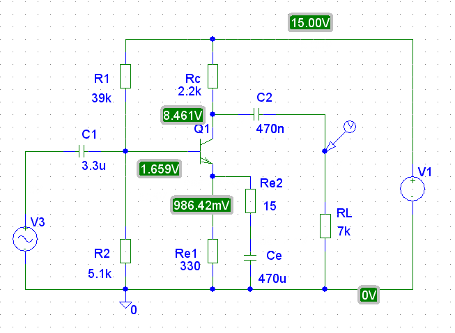
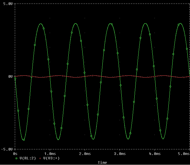
OK I have applied the capacitance values which you gave me & simulate the circuit I can see difference but the output signal does not look normal!
Also can you please give the equations you used for calculating C1 & C2. One more thing I forgot is that my instructor gave me this value (Vt=2.6mv) am not sure what is this & did not use it on any of my calculations. :confused:

I have attached the ORCAD .dsn file for my circuit so you can have a look at it in a better way but please note that I renamed the file & added extension ".zip" so forum uploaded can accept it so please rename it & delete the (.zip) so u can open with pspice
 

Attachments

Jony130

Joined Feb 17, 2009
5,488
The only given values are:
Voltage Gain= 70
Lower cutoff frequency= 70 Hz
Load Resistance= 7k ohm
Vce= 7v
Ic= 3mA
For this parameters it is better to use this schematic


I assume Ve = 1V and Vce = VRc = 7V, and β = 100.

Vcc = 1V + 2*7V = 15V

Rc = 7V/3mA = 2.2kΩ

Re1 = 1V/3mA = 330Ω

Vb = 3mA * 330Ω + 0.65V = 1.65V

Ib = 3mA/100 = 30
μA (base current)

R2 = Vb / ( 10 * Ib) = 5.1KΩ

R1 = ( Vcc - Vb) / ( 11 * Ib) = 39KΩ

So know if we want voltage gain 70V/V

Au = 70 = (Rc|| RL) / ( re + (Re1||Re2) )

( re + (Re1||Re2) ) = (Rc|| RL) / 70 = 1.6KΩ/70 = 22Ω

22Ω = ( 8.7Ω + (330||Re2) )

Re2 = ( 330 * 13.3 ) / (330 - 13.3) = 13.8 =[ B]15Ω[/B]

Lower cutoff frequency= 70 Hz, becaues we have three High Pass Filters connect in series.
We must design Fc = √ ((70^2) / 3)= 40Hz

C1 = 0.16/ ( 40Hz * R1||R2|| [ β+1 * ( re + (Re1||Re2) ) ) = 0.16/ ( 40 * 1.5K) = 2.6uF = 3.3uF

C2 = 0.16/(40Hz * (Rc+RL) ) = 470nF

Ce = 0.16/ ( 40Hz * Re2) = 333uF=470uF


Thread Starter

HARASI

Joined Apr 22, 2009
12
this is a very professional way but sadly I got it late & I saw the need of adding one more resistor Re2 which made the circuit give accurate output.. but I have used some different method which gave me different components values but output was 70 as needed.
 

Jony130

Joined Feb 17, 2009
5,488
Ok, so without change the schematics

Vce = 7V
Ic = 3mA
RL = 7K
Au = 70 V/V

Au = Rc||RL/re = Rc||7K / ( 26mV/3mA) = Rc||7K/8.7
Ω

Rc||RL = 70 * 8.7
Ω = 609Ω

Rc = (7K * 609) / (7K - 609) = 667.031763Ω = 680Ω

Re = 1V/3mA = 330Ω

Vcc = 1V + 7V + Ic*Rc = 10V

R2 = Vb / ( 10 * Ib) = 5.1KΩ

R1 = ( Vcc - Vb) / ( 11 * Ib) = 24KΩ

C1 =0.16/(Fc * R1||R2||(β+1)*re≈ 0.16/ ( 40Hz * 101*8.7Ω) = 4.7uF

C2 = 0.16/(Fc*Rc+RL) = 680nF

Ce = 0.16/( Fc * re) = 470uF
 

Attachments

Thread Starter

HARASI

Joined Apr 22, 2009
12
This one is great but I have some questions:
(((Au = Rc||RL/re = Rc||7K / ( 26mV/3mA) = Rc||7K/8.7Ω)))
where did you got the 26mv from?
(((C1 =0.16/(Fc * R1||R2||(β+1)*re≈ 0.16/ ( 40Hz * 101*8.7Ω) = 4.7uF)))
I believe fc is the cutoff freq. which was given as 70Hz but you have substituted 40Hz!! Am I right?
 

Jony130

Joined Feb 17, 2009
5,488
26mV is a thermal voltage
http://en.wikipedia.org/wiki/Boltzmann_constant#Role_in_semiconductor_physics:_the_thermal_voltage

(((C1 =0.16/(Fc * R1||R2||(β+1)*re≈ 0.16/ ( 40Hz * 101*8.7Ω) = 4.7uF)))
I believe fc is the cutoff freq. which was given as 70Hz but you have substituted 40Hz!! Am I right?
Yes I substituted 40Hz
Becaues in you amplifier you have three high pas filters connect in series.
So the net (equivalent)
cutoff freq. is equal:
Fc = √ (F1^2 + F2^2 + F3^3)
And you wont Fc= 70Hz, and if we assume F1=F2=F3 then

F1 = √(Fc^2)/3 = √(70^2)/3=√(4900/3) ≈ 40Hz

And we cheek the result

Fc = √ (F1^2 + F2^2 + F3^3) = √(40^2+40^2+40^2) =69Hz
 

Audioguru

Joined Dec 20, 2007
11,248
It is difficult to calculate the voltage gain from the output to input ratio because the output has 20% to 30% distortion. Its positive-going peaks are compressed.

Here is an example of the distortion:
 

Attachments

Thread Starter

HARASI

Joined Apr 22, 2009
12
I did the simulation & added Vin/Vout as my Trace on pspice. It gave me almost 70 if we ignore distortions. I think it is close enough.

Finally am done with my project & submitted the final report today. Appreciate your help guys.
 
Top