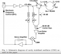
Hello, I am trying to understand the logic of a schematics shown bellow taken from the attched article.
double-balanced mixer shown bellow is turned into a phase detector when one signal is shifter 90 degrees with respects to the other.
We have our noisy YIG source (f0+noise) it gets into two routes :
1. going into the cavity oscilator producing pure f0
2.shifted by 90 degrees, so (f0+noise)+90 degree shift
we supress the main tone returned pure signal froms oscilator
So as i see it we have inside our phase detector two signals:
1.returned cavity oscilator signal with supressed carried(so basicly noise)
2.original YIG source (f0+noise) with 90 degree shift
What result do we expect? we compare pure noise to f0+noise with a shift.
they are totally different .
I cant see the physical logic in this comparison.
Thanks.

Attachments
-
563.8 KB Views: 2


