Cavity magnetron waveguide

Thread Starter

HotFurnace

Joined Mar 31, 2018
29
Hi all,
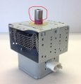
My parent microwave recently broke down, so I have the opportunity to fix it. After figured out that the magnetron have leaked, I replaced the tube and teared down the old tube. During the teardown, I have taken apart the waveguide? (see waveguide.jpg) and reveal the internal part. It seem to be a sealed copper tube, part of the anode? (see removed.jpg) Anyone have ideas what are these? How could radiowave escape from that copper tube to enter the oven cavity?
 

Attachments

Thread Starter

HotFurnace

Joined Mar 31, 2018
29
How would that works? How could an antenna is as simple as a sealed copper tube? I believe there must be something inside the tube?
 

Ramussons

Joined May 3, 2013
1,404
Microwaves do not need a "conductor" to traverse through a Waveguide. The waveguide "Guides" the Electromagnetic signals (Hence the term Wave-Guide). The EM signals flow like water in a pipe. The waveguides can be Rectangular, Square, Elliptical or Round and the Dimensions depend on the Frequency of the Microwave Dignal.
 

CharlesWMcDonald

Joined May 16, 2019
233
Inside the tube are cavities arranged radially and open toward the center. The cathode is in the center and the anode is the outside of the copper tube. Strong magnets are placed above and below the cavities. When a high voltage negative pulse is applied to the cathode electrons flow from the anode toward the cathode but are diverted in a circular path by the magnetic field. As they move across the opening of a cavity they cause the cavity to resonate. Conductor rings across the top of the cavity conduct the microwave to a conductor that goes up into the antenna. (top of the magnetron) The antenna couples the microwaves to the waveguide.
 

Thread Starter

HotFurnace

Joined Mar 31, 2018
29
Microwaves do not need a "conductor" to traverse through a Waveguide. The waveguide "Guides" the Electromagnetic signals (Hence the term Wave-Guide). The EM signals flow like water in a pipe. The waveguides can be Rectangular, Square, Elliptical or Round and the Dimensions depend on the Frequency of the Microwave Dignal.
I have identified the waveguide and of course it function, but i just wonder why a sealed copper tube is in place. This is of course not the waveguide.
An antenna can be as simple as a 'special' length of copper tube as the feed coupling to a wave guide.


http://www.radartutorial.eu/03.linetheory/tl11.en.html

If that copper tube is really an antenna then i expect it to be connected to the feedpoint, not the anode of the magnetron? There is zero ohm between the copper tube and the anode.
Inside the tube are cavities arranged radially and open toward the center. The cathode is in the center and the anode is the outside of the copper tube. Strong magnets are placed above and below the cavities. When a high voltage negative pulse is applied to the cathode electrons flow from the anode toward the cathode but are diverted in a circular path by the magnetic field. As they move across the opening of a cavity they cause the cavity to resonate. Conductor rings across the top of the cavity conduct the microwave to a conductor that goes up into the antenna. (top of the magnetron) The antenna couples the microwaves to the waveguide.
So there is a metal ring on top of every cavities inside the magnetron, and a metal conductor connect those rings to the antenna. And where is the antenna? Inside that copper tube or the copper tube itself?
 

nsaspook

Joined Aug 27, 2009
13,086
I have identified the waveguide and of course it function, but i just wonder why a sealed copper tube is in place. This is of course not the waveguide.

If that copper tube is really an antenna then i expect it to be connected to the feedpoint, not the anode of the magnetron? There is zero ohm between the copper tube and the anode.

So there is a metal ring on top of every cavities inside the magnetron, and a metal conductor connect those rings to the antenna. And where is the antenna? Inside that copper tube or the copper tube itself?
It's the copper tube itself. A DC resistance of zero DOES NOT mean a AC impedance of zero at the antenna resonant frequency because there is a phase difference between points on the tube as the RF fields move around the tube.
 

Thread Starter

HotFurnace

Joined Mar 31, 2018
29
Here is a very good description of the way a magnetron works.

http://www.radartutorial.eu/08.transmitters/Magnetron.en.html

This one is specific to microwave ovens.

Indeed it is, I see there's a loop in one of the cavities to exact microwave energy, but why just one?
It's the copper tube itself. A DC resistance of zero DOES NOT mean a AC impedance of zero at the antenna resonant frequency because there is a phase difference between points on the tube as the RF fields move around the tube.
I just have saw the copper tube from your picture, it is leading downward, from the ceramic holding the waveguide into one cavity. But how it end up inside that cavity is unclear. So the antenna is the copper tube, but how it end up inside the cavity? Forming a loop inside the cavity? I don't think so, since the space inside the cavity is too small for the tube to be bended around.
 

nsaspook

Joined Aug 27, 2009
13,086
Indeed it is, I see there's a loop in one of the cavities to exact microwave energy, but why just one?

I just have saw the copper tube from your picture, it is leading downward, from the ceramic holding the waveguide into one cavity. But how it end up inside that cavity is unclear. So the antenna is the copper tube, but how it end up inside the cavity? Forming a loop inside the cavity? I don't think so, since the space inside the cavity is too small for the tube to be bended around.
You can have either a voltage (e-field) node feed using a 1/4 λ stub or a current (m-field) node feed using a loop.
Again...
http://www.radartutorial.eu/03.linetheory/tl11.en.html
 

Janis59

Joined Aug 21, 2017
1,834
Actually we had few years ago here one extremely interesting project about 2,4 GHz magnetron line= launcher+circulator+three knob impedance adjuster plus last slightly secret object. But whole project was broken to scrap just because simplest WR430 steels parcel demand about 5K of cabbages. WHY those piece of s** with slightly altered accuracy and special surface coatings EVERY every every piece have price between 1000 and 3000 Eur? No wonder that cooker producers make waveguides themselves - with no accuracy and no coatings.
 

Thread Starter

HotFurnace

Joined Mar 31, 2018
29
Actually we had few years ago here one extremely interesting project about 2,4 GHz magnetron line= launcher+circulator+three knob impedance adjuster plus last slightly secret object. But whole project was broken to scrap just because simplest WR430 steels parcel demand about 5K of cabbages. WHY those piece of s** with slightly altered accuracy and special surface coatings EVERY every every piece have price between 1000 and 3000 Eur? No wonder that cooker producers make waveguides themselves - with no accuracy and no coatings.
It would be interesting to measure the efficiency of those waveguide with these expensive proprietary steel work in comparison to simple, homemade waveguide. I think it must have obvious advantage to justify the cost. Or they just sell it to the military, who are willing to spend a lot of money?
 

nsaspook

Joined Aug 27, 2009
13,086
It would be interesting to measure the efficiency of those waveguide with these expensive proprietary steel work in comparison to simple, homemade waveguide. I think it must have obvious advantage to justify the cost. Or they just sell it to the military, who are willing to spend a lot of money?
It makes a difference when you're looking at long feed-lines and low return signal levels. A precision polish and gold plating are important to reduce skin-effect resistivity losses and to maintain special pulse compression waveforms.
 
Top