Facebook
 Google
 GitHub
 Linkedin
Hi All,
First post and hoping somebody can help me get my factory amp running again... it’s been awful quiet in the car the last few weeks...
The amp is part of a factory Bose system which failed recently. A bit of internet research showed the most likely culprits were a voltage regulator, digital signal processor and surround sound codec.
I’ve managed to find all three parts and started replacing the voltage regulator first as it is the most common failure.
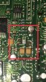
I have successfully removed the DF8 IC but am now left with some dark patches where it was. All of the traces and solder pads look ok for the pins that are used in the data sheet pinout, but where the NC pins are there are these dark marks. I assumed they were solder pads or traces that I pulled off being to heavy handed but why would there be pads if the pins are not used? Are they normally grounded or something to prevent noise?
If not what are they likely to be and do I need to repair them or will the circuit work without them?
I have learned a lot getting this far and really enjoyed it but don’t really know how the board would normally look under the chip and the only images I can find online only show it with the chip in place.
The pinout is below with a photo of the board. The chip should be oriented with the dot and top edge along the the two yellow capacitors.
For anyone with a keen eye there is a very small sm capacitor missing from the input pin as I removed it to give a little more space for my iron.
Any help greatly appreciated


First post and hoping somebody can help me get my factory amp running again... it’s been awful quiet in the car the last few weeks...
The amp is part of a factory Bose system which failed recently. A bit of internet research showed the most likely culprits were a voltage regulator, digital signal processor and surround sound codec.
I’ve managed to find all three parts and started replacing the voltage regulator first as it is the most common failure.
I have successfully removed the DF8 IC but am now left with some dark patches where it was. All of the traces and solder pads look ok for the pins that are used in the data sheet pinout, but where the NC pins are there are these dark marks. I assumed they were solder pads or traces that I pulled off being to heavy handed but why would there be pads if the pins are not used? Are they normally grounded or something to prevent noise?
If not what are they likely to be and do I need to repair them or will the circuit work without them?
I have learned a lot getting this far and really enjoyed it but don’t really know how the board would normally look under the chip and the only images I can find online only show it with the chip in place.
The pinout is below with a photo of the board. The chip should be oriented with the dot and top edge along the the two yellow capacitors.
For anyone with a keen eye there is a very small sm capacitor missing from the input pin as I removed it to give a little more space for my iron.
Any help greatly appreciated