 Facebook
 Google
 GitHub
 Linkedin
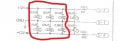
I'm creating a repro of a small pcb. The original design (from the 80s) has 3 .1uF capacitors in parallel. To save space on the board, I want to replace the 3 .1uF with a single .33uF. Am I correct in thinking the new version is equivalent? I've attach snippets of the original design and mine. Thanks
Attachments
-
 33.2 KB Views: 27
 -
 42.8 KB Views: 28
")


