Capacitor Symbols

Thread Starter

biferi

Joined Apr 14, 2017
540
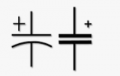
I was looking up Capacitor Symbols and I came up with one that is 2. Lines next to one another.

Then I came up with one that is 1. Line and the Line next to it is bent.

These are the Capacitor Symbols I need?

Fixed Ceramic Disk Capacitor Bidirectional.
Fixed Electrolytic Dry Capacitor Unidirectional.
Fixed Electrolytic Wet Capacitor Unidirectional.
Fixed Polyester Film Dry Capacitor Bidirectional.
Fixed Mica Capacitor Bidirectional.
 

MaxHeadRoom

Joined Jul 18, 2013
30,848
If one plate is curved, then this notifies that one (this) side is the ground reference connection of the cap.
The polarized versions are typically electrolytic, look up this term for the symbol.

1791309236478.png
 
Last edited:

ericgibbs

Joined Jan 29, 2010
21,591
hi bi
Google link
E
https://www.google.com/search?clien...+of+the+differnt++symbols+used+for+capacitors


clip:

Different capacitor schematic symbols communicate the component's polarity, adjustability, and function within an electronic circuit. [1, 2]
The primary purpose of each distinct symbol is outlined below:

Non-Polarized (Fixed) Capacitors
    • Symbol: Two straight, parallel lines.
    • Purpose: Indicates a standard component like a ceramic or film capacitor that has no positive or negative terminal. It can connect in either direction and is used for AC coupling, filtering high-frequency noise, and timing. [1, 2, 3]

Polarized (Electrolytic/Tantalum) Capacitors
    • Symbol: One straight line and one curved line, often accompanied by a plus (+) sign.
    • Purpose: Dictates strict voltage orientation. The positive terminal (anode) must connect to a higher potential than the negative terminal (cathode) to prevent overheating, leakage, or explosion. These offer high capacitance values for bulk power supply filtering and DC smoothing. [1, 2, 3]

Variable Capacitors
    • Symbol: Two parallel lines crossed by a diagonal arrow.
    • Purpose: Shows that the capacitance can be manually tuned or adjusted during standard device operation (such as tuning radio frequencies). [1]

Trimmer Capacitors
    • Symbol: Two parallel lines with a T-shaped or perpendicular line/arrow modifier.
    • Purpose: Represents a miniature variable capacitor adjusted once during factory calibration or troubleshooting, rather than by the end user. [1]
 

crutschow

Joined Mar 14, 2008
38,859
The two symbols I mostly use [commonly used USA [non-European] symbols from LTspice):

Any non-polarized (arbitrary orientation in circuit with respect to voltage polarity)
1791313176932.png
Any polarized (usually Electrolytic types where + side must never have a negative voltage with respect to the other terminal)
1791313195741.png
 
Last edited:

boostbuck

Joined Oct 5, 2017
1,065
"In some older or specific regional standards, a curved plate can also denote the outer foil plate of a non-polarized capacitor (like a paper or film type) for shielding purposes "
 

MaxHeadRoom

Joined Jul 18, 2013
30,848
This shows two caps, and both intended to be polarized, but the first one (LH) is usually a ceramic type and the outer termination should be connected to GND in decoupling circuits et otherwise it will not matter, with the RH version is usually electrolytic where polarity matters to avoid destruction. (see post #2)
1791339266129.png
 

crutschow

Joined Mar 14, 2008
38,859
During my 40 years of engineering career (so far) ALL of the information that I have needed to convey about capacitors has been stated in the materials list, which sometimes also included make and model. Not an area for purchasing to decipher!
Don't understand how that's pertinent to the discussion about capacitor symbols. :rolleyes:
 
KiCad's take on it. KiCad implies the curved line is a US standard. Presumably most other countries use the other form. I'm from the UK and have never used the curved line versions.

1791358266216.png
 
My point in my previous post was that the symbol is ONLY an assist to help understand the drawing. and that the actual details are elsewhere. so the symbol details are an assist, not the last word.
 
Last edited:
I was looking up Capacitor Symbols and I came up with one that is 2. Lines next to one another.

Then I came up with one that is 1. Line and the Line next to it is bent.

These are the Capacitor Symbols I need?

Fixed Ceramic Disk Capacitor Bidirectional.
Fixed Electrolytic Dry Capacitor Unidirectional.
Fixed Electrolytic Wet Capacitor Unidirectional.
Fixed Polyester Film Dry Capacitor Bidirectional.
Fixed Mica Capacitor Bidirectional.
The two symbols you found are not enough to identify these capacitor types.

A capacitor with two straight plates represents a fixed, non-polarized capacitor. This applies to ceramic, polyester film, and mica capacitors.

Electrolytic capacitors are polarized. Their symbol normally shows a positive + terminal or another polarity indication.

The ceramic disk, polyester film, and mica capacitors use the non-polarized symbol. Both dry and wet electrolytic capacitors use a polarized symbol.

In this article you will find all nitty gritty stuff about All Types of capacitor symbols.
 
The two symbols you found are not enough to identify these capacitor types.

"A capacitor with two straight plates represents a fixed, non-polarized capacitor. This applies to ceramic, polyester film, and mica capacitors.

Electrolytic capacitors are polarized. Their symbol normally shows a positive + terminal or another polarity indication.

The ceramic disk, polyester film, and mica capacitors use the non-polarized symbol. Both dry and wet electrolytic capacitors use a polarized symbol."

In this article you will find all nitty gritty stuff about All Types of capacitor symbols.
IN actual ellectrical circuit drawings used by actual large companies, to document actual electrical equipment used, the
standard symbols used in most endustrial electical circuit drawings, two straight lines represents a control relay contact or a motor starter AC contact. So one curved line plus one straight line is utilized to provide a different symbol for capacitors.
Those who choose to use two parallel straight lines for a capacitor symbol simply add a bit of confusion for those who need to quickly understand a drawing.
In all industrial applications, capacitor types and specifications are provided in actual TEXT notes on drawings.

The reason being that not everybody is familiar with all of the secret symbol meanings.
 
In this article you will find all nitty gritty stuff about All Types of capacitor symbols.
Here it is another webpage which identifies further capacitor types and drawing styles. In my youth I used to repair Japanese consumer electronics, so I was very familiar (and personally like) the Japanese-style electrolytic capacitor.

https://mozelectronics.com/tutorials/capacitor-basic-capacitor-symbol/

Additionally, old Soviet schematics would have an additional variant, although not seen very often in the West. Description from Google, which unfortunately didn't provide images:

Polarized (Electrolytic) Capacitor: Drawn using one thin line alongside a hollow, unshaded rectangle to designate polarity. Alternatively, it can be drawn as two standard parallel lines with a prominent "+" sign placed explicitly next to the positive plate
 
To understand the function of a circuit, only the value of a passive component needs to be known. Of course, to service or repair a system, more detail is required to providea correct replacement. To costruct a copy of what the circuit depicts, even more information is required, but that is best included in a separate text listing of items.
In many aspects the reading and understanding of a circuit is much like the reading and understanding of a language, but with symbols replacing words, and connection lines replacing the sentence word sequences. In circuits there are many fewer "words" than in other languages, andoften the meanings are more clear.
 

MaxHeadRoom

Joined Jul 18, 2013
30,848
I have always used the standard reference designators as laid out by ANSI/IEEE etc and IEC/ISO standard component designators.
Also as laid out in NFPA79.
Which usually leaves pretty much little uncertainty.
Drawings that use these standards do not generally leave any uncertainty, as far as I have experienced anyway :rolleyes:
 
I have always used the standard reference designators as laid out by ANSI/IEEE etc and IEC/ISO standard component designators.
Also as laid out in NFPA79.
Which usually leaves pretty much little uncertainty.
Drawings that use these standards do not generally leave any uncertainty, as far as I have experienced anyway :rolleyes:
How do those compare with the capacitor symbols we see in post #16??
 

MaxHeadRoom

Joined Jul 18, 2013
30,848
Compare or identify? all using the C identifier?
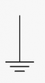
The prime example of symbol missuse is the Earth GND symbol, where it is almost universally used for power common!
A publication that uses it throughout and should know better is the "Art of Electronics" :confused:

1791498860983.pngEarth GND
 
Top