 Facebook
 Google
 GitHub
 Linkedin
Hello,
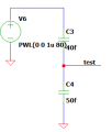
I am working on a project which contains a capacitive voltage divider. I wanted to test it, so I made a simple schematic with 2 capacitors in series and a voltage source and I wanted to look at the voltage between the two. Let's say the supply is VDD and the capacitors are of the same value. So the voltage should be 1/2 VDD. The problem is, the voltage drops to nearly 0V after some time. Theoretically there is no way it should discharge like that. The capacitors and the source are ideal, I did the simulation in LTSpice. Does someone have an explanation for this and how could I fix it? I attached the schematic but as I said it is really simple.
I am working on a project which contains a capacitive voltage divider. I wanted to test it, so I made a simple schematic with 2 capacitors in series and a voltage source and I wanted to look at the voltage between the two. Let's say the supply is VDD and the capacitors are of the same value. So the voltage should be 1/2 VDD. The problem is, the voltage drops to nearly 0V after some time. Theoretically there is no way it should discharge like that. The capacitors and the source are ideal, I did the simulation in LTSpice. Does someone have an explanation for this and how could I fix it? I attached the schematic but as I said it is really simple.
Attachments
-
 4.6 KB Views: 64
 I know it's really small, but it is what it is.


