For what it's worth, I still think considering a much lower square wave frequency would be a good idea, unless you really need the high frequency for some reason.
For what it's worth, I still think considering a much lower square wave frequency would be a good idea, unless you really need the high frequency for some reason.
The recommended frequency would depend on several factors. The first two that come to mind are:
1) What do you plan to do with the information you read from this sensor? How often do you need new, fresh input data in order for the rest of your system to respond as needed? In other words, if we ignore the specifics of this circuit for a moment, what kind of speed and response time does the rest of your system actually need from this level sensing circuit?
2) What is the nature of the probe/sensor that is connected to the op amp circuit you've designed?
I've had a hard time understanding the details in this thread so far, but here is what I thought you'd said previously:
1) Water level detection, which in my past experience usually means either:
A) checking water level in order to open a valve and refill something when level gets too low, or
B) checking level to shut off something else when level gets too low (for example, a heating element that can't be run safely unless it's fully submerged in water.
2) I've been assuming that your "sensor" was literally just a metal probe at a chosen height within your water storage, such that when water level is low, metal probe is electrically "floating" and totally isolated from water, and when water level is higher, probe is touching water so that there's a conductive path from water directly to circuit input. @Alec_t suggested in the last post that you were using a capacitive water level detection circuit - if that's the case it would change my assumptions.
Now, if my assumptions are correct, you don't need a fast response time because valves can't open and close fast enough to do anything with faster input data anyway, and a conductive probe touching water doesn't have any particular speed requirements. In that case, I'd recommend much lower rates, maybe 10-100Hz max, with capacitors and resistors adjusted accordingly.
If my assumptions aren't correct, PLEASE give us a more detailed description of what this circuit is trying to accomplish, how fast and how often it needs to do it, and what your sensor or probe is (including specs, part number, datasheet etc if it's anything more than just a stick of metal.)
Finally, you say you got the same observation at 500Hz? What do you mean by "same observation?" Surely you're not saying that it still looks like a sawtooth or triangle wave? Are you simply not seeing the voltages you hoped for? Are you seeing individual spikes like way back in post 43? It's hard to diagnose what's going wrong at 500Hz without knowing what you're seeing at 500Hz, and also what you think you should be seeing at 500Hz.
Gain-bandwidth-product, and slew-rate are the two primary specifications covering an opamp's frequency response.
The type of divider really doesn't have any direct effect on the opamp response requirements.
The recommended frequency would depend on several factors. The first two that come to mind are:
1) What do you plan to do with the information you read from this sensor? How often do you need new, fresh input data in order for the rest of your system to respond as needed? In other words, if we ignore the specifics of this circuit for a moment, what kind of speed and response time does the rest of your system actually need from this level sensing circuit?
2) What is the nature of the probe/sensor that is connected to the op amp circuit you've designed?
I've had a hard time understanding the details in this thread so far, but here is what I thought you'd said previously:
1) Water level detection, which in my past experience usually means either:
A) checking water level in order to open a valve and refill something when level gets too low, or
B) checking level to shut off something else when level gets too low (for example, a heating element that can't be run safely unless it's fully submerged in water.
2) I've been assuming that your "sensor" was literally just a metal probe at a chosen height within your water storage, such that when water level is low, metal probe is electrically "floating" and totally isolated from water, and when water level is higher, probe is touching water so that there's a conductive path from water directly to circuit input. @Alec_t suggested in the last post that you were using a capacitive water level detection circuit - if that's the case it would change my assumptions.
Now, if my assumptions are correct, you don't need a fast response time because valves can't open and close fast enough to do anything with faster input data anyway, and a conductive probe touching water doesn't have any particular speed requirements. In that case, I'd recommend much lower rates, maybe 10-100Hz max, with capacitors and resistors adjusted accordingly.
If my assumptions aren't correct, PLEASE give us a more detailed description of what this circuit is trying to accomplish, how fast and how often it needs to do it, and what your sensor or probe is (including specs, part number, datasheet etc if it's anything more than just a stick of metal.)
Finally, you say you got the same observation at 500Hz? What do you mean by "same observation?" Surely you're not saying that it still looks like a sawtooth or triangle wave? Are you simply not seeing the voltages you hoped for? Are you seeing individual spikes like way back in post 43? It's hard to diagnose what's going wrong at 500Hz without knowing what you're seeing at 500Hz, and also what you think you should be seeing at 500Hz.
Yes. But if the capacitance values are small, any stray circuit capacitance will affect the division ratio significantly. Also, the ratio could be affected in a frequency-dependent way by resistive loading of the divider.
Are you taking the input impedance and bandwidth of your 'scope into account?
Most op-amp devices will not provide adequate performance unless used within their published limits. This means, among other things, that both the input voltage range and the output voltage range must be less than the power supply voltage. Also, the use of a square wave adds frequency response requirements much higher than the input frequency. But the simulation program will not warn you about any of this.
Sorry for slow response. I normally get email notifications for replies on threads, and I didn't see any for this (not accusing forum of messing up - I may have just overlooked them.)
Anyway, let me just make sure I'm understanding things correctly. At this point:
you're running at a lower frequency
you've got a nice square wave output
the voltage division is pretty close to what you want (any error could just be capacitor tolerances, or stray capacitance as @Alec_t pointed out.)
So now the only problem is that you want the square wave to essentially disappear when the probe is grounded out, and instead you're seeing little, if any, effect. Is that correct?
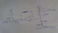
If so, double check where and how you're connecting the probe to the rest of the circuit. As drawn in your most recent post, it makes sense that the probe would have no effect, because both sides of it connect to the same node, which is already ground. If you connect the probe across (in parallel with) the lower capacitor in your divider, it should ground out the input signal.
Sorry for slow response. I normally get email notifications for replies on threads, and I didn't see any for this (not accusing forum of messing up - I may have just overlooked them.)
Anyway, let me just make sure I'm understanding things correctly. At this point:
you're running at a lower frequency
you've got a nice square wave output
the voltage division is pretty close to what you want (any error could just be capacitor tolerances, or stray capacitance as @Alec_t pointed out.)
So now the only problem is that you want the square wave to essentially disappear when the probe is grounded out, and instead you're seeing little, if any, effect. Is that correct?
If so, double check where and how you're connecting the probe to the rest of the circuit. As drawn in your most recent post, it makes sense that the probe would have no effect, because both sides of it connect to the same node, which is already ground. If you connect the probe across (in parallel with) the lower capacitor in your divider, it should ground out the input signal.
Congratulations! What did you change in order to get it to do what you wanted? (This thread will be much more helpful to others in the future if they know what the final solution was!)
Also, I'm a little surprised that that's the waveform you wanted. Is that with the probe shorted or probe open? What does the signal look like in the other state?
Regardless of the answers to my questions above, congratulations!
 Facebook
 Google
 GitHub
 Linkedin