Facebook
 Google
 GitHub
 Linkedin
Hi all,
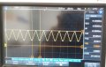
I am opening this thread with actual tested results.
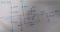
Please find attached waveform & schematic.
I did not get expected results as per simulation.
Please help me out to get the right results.
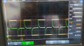
CH1(yellow) : PWM Signal
CH2(green) : Opamp output
use shorting link in place of sensor as done in above simulation.
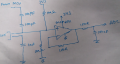
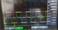
I am opening this thread with actual tested results.
Please find attached waveform & schematic.
I did not get expected results as per simulation.
Please help me out to get the right results.
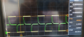
CH1(yellow) : PWM Signal
CH2(green) : Opamp output
use shorting link in place of sensor as done in above simulation.
Attachments
-
 11.8 KB Views: 13
 -
 14.6 KB Views: 13