Capacitive divider interfaced with ADC - Help needed in board debugging

Thread Starter

mishra87

Joined Jan 17, 2016
1,034
Thank you very much for your quick response !!!

I beg a pardon if I am doing more R&D on that.
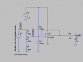
I replace the resistance with capacitance of 100pf, 100pf & 1nf in divider network and rest of the circuit remains same.
Reactance of C1(i.e. 100pf) is xc1 = 15.92K for 100KHz
Reactance of C2(i.e. 100pf) is xc2 = 15.92K for 100KHz
Reactance of C3(i.e. 1nf) is xc3 = 1.59K for 100KHz

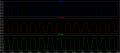
Case 1 : Now I tried to do simulation but this time I got different behavior. There is voltage swing at ADC from 1.8V to 3.2V. and at divider point voltage swing is 1.8V to 3.6V.
upload_2019-6-2_14-2-23.png
upload_2019-6-2_14-3-2.png

Case 2:
upload_2019-6-2_14-5-25.png
upload_2019-6-2_14-5-43.png

Regards,
 

Alec_t

Joined Sep 17, 2013
14,313
The non-inverting input is floating and its DC level is indeterminate.
If you do use a capacitive divider you will still need to provide a current path for the bias current of the non-inverting input of the opamp. For a unity gain buffer, with the inverting input tied to the output, the output provides the required bias current path for the inverting input. Why do you want a capacitive divider?
 
Last edited:

Thread Starter

mishra87

Joined Jan 17, 2016
1,034
If you do use a capacitive divider you will still need to provide a current path for the bias current of the non-inverting input of the opamp. For a unity gain buffer, with the inverting input tied to the output, the output provides the required bias current path for the inverting input. Why would you want a capacitive divider?
Thanks Mr. Alec_t for your reply.

There is two cases : 1) C1 And C2+C3 makes divider network 2) Signal directly goes to opamp non inverting terminal I don't think so its floating.

I want interface level sensor with MCU ADC using capacitive divider.
Could you explain in circuit how one can give current path in circuit to achieve the objective.

I think we have two way to achieve this : And that is depend upon types of enclosure used i.e. metallic or plastic.
1) resistive divider
2) capacitive divider

As I simulated for resistive divider can we achieve the results for capacitive divider. Is it possible for practical applications.

Thanks & regards,
 
Last edited:

Thread Starter

mishra87

Joined Jan 17, 2016
1,034
I don't see any changes in output voltage if C3 is connected and if C3 is not connected for capacitive divider.

Regards,
 

Alec_t

Joined Sep 17, 2013
14,313
I don't think so its floating.
As far as DC is concerned it is floating. Try connecting a 1meg resistor from the non-inverting input to the positive supply, and another 1 meg resistor from that input to ground. They will bias the input at about half the supply voltage and provide the necessary DC bias current path.
I don't see any changes in output voltage if C3 is connected and if C3 is not connected for capacitive divider.
I'm not surprised, as the opamp shown is not biased correctly.
 

Thread Starter

mishra87

Joined Jan 17, 2016
1,034
As far as DC is concerned it is floating. Try connecting a 1meg resistor from the non-inverting input to the positive supply, and another 1 meg resistor from that input to ground. They will bias the input at about half the supply voltage and provide the necessary DC bias current path.

I'm not surprised, as the opamp shown is not biased correctly.
Thanks for your reply Mr. Alec_t..
You people are really guiding unknowingly young Engineers like me.

Now come to the point, I made the changes suggested by you but still unable to meet the results . below is the simulation data.
1. I do not see output swing to 1/2Vcc of either two cases. Could you suggest where am I making mistake.
upload_2019-6-3_17-11-44.png
upload_2019-6-3_17-12-10.png

2.
upload_2019-6-3_17-13-10.png
upload_2019-6-3_17-13-35.png

Hope to hear you soon !!!
 

Alec_t

Joined Sep 17, 2013
14,313
I do not see output swing to 1/2Vcc of either two cases. Could you suggest where am I making mistake.
It looks ok to me. The output peak-to-peak voltage is about 1.65V (1/2 Vcc) centred around 1.7V (~1/2 Vcc).
With C2 and C3 having comparatively low values your divider is subject to error due to stray capacitance at the opamp inputs.
What is the purpose of C5 and R1?
 
Last edited:

Thread Starter

mishra87

Joined Jan 17, 2016
1,034
It looks ok to me. The output peak-to-peak voltage is about 1.65V (1/2 Vcc) centred around 1.7V (~1/2 Vcc).
With C2 and C3 having comparatively low values your divider is subject to error due to stray capacitance at the opamp inputs.
What is the purpose of C5 and R1?
Thanks for your reply .!

I think your are talking about C4 & R1.

The signal is going to connect with STM32F ADC and it's sample and hold capacitor . Sample switch resistance which comes into picture once you connect your signal to ADC pin as per my understanding . That is why I connected C4 and R1 at opamp output to see the opamp actual behavioural.

What value would you suggest for C2 & C3 for this application.

Regards,
 

Alec_t

Joined Sep 17, 2013
14,313
What value would you suggest for C2 & C3 for this application.
Can't say definitely, as the signal source characteristics are a complete mystery. I'd suggest 1nF, to be well above stray capacitance level, but will the source tolerate that?
You still haven't said why you are using a capacitive divider instead of a resistive divider.
What is the purpose of C5?
 

Thread Starter

mishra87

Joined Jan 17, 2016
1,034
Can't say definitely, as the signal source characteristics are a complete mystery. I'd suggest 1nF, to be well above stray capacitance level, but will the source tolerate that?
You still haven't said why you are using a capacitive divider instead of a resistive divider.
What is the purpose of C5?

Capictive divider going to be used as a level sensor. To sense the level of conductive liquid.

C5 will provide a current path when any conductice probes comes in contact with conductive path .

When there is no contact between probe and conductive liquid C5 left unconnected .

I hope this helps in discussion.Real time application could be water purifier.

Thanks !!!
 

Alec_t

Joined Sep 17, 2013
14,313
Capictive divider going to be used as a level sensor. To sense the level of conductive liquid
In that case 1nF seems non-realisable and even 100p might be optimistic if that is electrode/liquid capacitance. So you'd need to take steps to minimise stray capacitance .
 

Thread Starter

mishra87

Joined Jan 17, 2016
1,034
In that case 1nF seems non-realisable and even 100p might be optimistic if that is electrode/liquid capacitance. So you'd need to take steps to minimise stray capacitance .
Hope you understood, what am i trying to say. If not so i will explain a bit more.

Yes , there might be C5=100pF capacitance for optimistic results. But now output of divider is 2/3Vcc when C5 is connected because C5=100pF doubles the reactance of lower divider i.e C3+C5 and If C5 left floating Vcc suppose to be appeared to ADC pin if i am correct. Now there is not much headroom when probe makes contact and when probe does not makes contact.

My intention was to connect C=1nF was to reduce the impact of capacitive reactance in capacitive divider network so there could equal voltage drop across both capacitor.

I am not sure whether i am right or wrong track its you people showing me the way to come up my ideas.

Regards,
 

Thread Starter

mishra87

Joined Jan 17, 2016
1,034
Simulation results of C2=C3=C5 =100p
One more thing i want to know, Is opamp buffer essential to have in the circuit. Can we directly connect the capacitor divider MCU ADC.

1. I still unable to understand why does the opamp output is 2.7V peak-peak and an AC is superimposed with 0.4Vdc. It should be 2.2V or 1/2Vcc = 1.65V
upload_2019-6-4_21-12-2.png
upload_2019-6-4_21-12-44.png

2. Simulation 2 looks fine to me. Only 600mV headroom in simulation 1 and simulation 2 results .

upload_2019-6-4_21-18-22.png
upload_2019-6-4_21-19-12.png

Regards.
 

Attachments

Daniel Sala

Joined May 28, 2015
65
Gain bandwidth: Caveat emptor, completely - Read the small print carefully by looking at the phase/closed loop gain graph(s) in the datasheet. Easy beginner error is thinking 1MHz bandwidth in sales pitch blurb on page 1 or on vendor site is just that, it isn't - 1MHz means gain of 0 at 1 MHz, more likely the op amp will be useful to you up to about e.g. 10kHz to 100kHz...

Can't remember if this has been mentioned already: faster op amp means higher supply current, as ever with electronics have to find happy medium between several desired conditions and the disappointing realistic acceptance of juggling a compromise between them that may be a little less than desired in individual features.
 

Alec_t

Joined Sep 17, 2013
14,313
I still unable to understand why does the opamp output is 2.7V peak-peak and an AC is superimposed with 0.4Vdc.
It is not 2.7V peak-to-peak. It is 2.66V-0.48V = 2.18V peak-to-peak, which is pretty close to the theoretical 2.2V. The opamp imperfections account for the difference and any DC offset.
Since the impedance of 100pF at 100kHz is about 16kΩ I think the buffer amp would be needed in your application, because many ADC inputs specify a source impedance less than 10kΩ to give accurate results. Check the datasheet for your ADC.
 
Last edited:

ebeowulf17

Joined Aug 12, 2014
3,307
Capictive divider going to be used as a level sensor. To sense the level of conductive liquid.

C5 will provide a current path when any conductice probes comes in contact with conductive path .

When there is no contact between probe and conductive liquid C5 left unconnected .

I hope this helps in discussion.Real time application could be water purifier.

Thanks !!!
Be careful using conductivity to sense water when you're purifying the water... the closer the water is to pure, the lower its conductivity. Really pure water will be very difficult to detect!
 
Top