Capacitive divider interfaced with ADC - Help needed in board debugging

Thread Starter

mishra87

Joined Jan 17, 2016
1,034
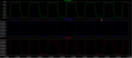
I want to give resistor divider signal to micro-controller ADC using opamp buffer to provide low impedance to ADC channel.
Now there is two scenario.

In scenario-1 the voltage across divider (V_divider) is not half of input voltage and voltage across ADC (V_ADC) is not equal to divider voltage.

upload_2019-5-31_22-20-35.png
upload_2019-5-31_22-22-16.png

In scenario-2 , R3 is removed now.
Why does the V_divider is equal to V_Input and V_ADC is equal to V_divider.
Could anybody correct the simulation for actual results.upload_2019-5-31_22-27-14.png upload_2019-5-31_22-26-36.png
upload_2019-5-31_22-27-14.png

Thanks in Advance !!!!

LT-Spice File Uploaded here .
 

Attachments

Last edited by a moderator:

crutschow

Joined Mar 14, 2008
34,280
How do you expect the circuit to work with one input of the op amp left floating?
Op amps can't work with one input open as the voltage is undefined.
Connect the feedback from the output back to the (-) input instead of the (+).

Also you need to use a single-supply op amp that can operate with a 3.3V supply.
 
Last edited:

Thread Starter

mishra87

Joined Jan 17, 2016
1,034
Thanks Mr. crutschow for your reply.

Yes , I made mistake and corrected now.
Could you suggest which single supply opamp to be used for this design.
Could you simulate some waveform and attached herewith because i tried simulation available opamp with LT spice i did not get exact results.
Below is simulation results now.

upload_2019-6-1_9-51-57.png
upload_2019-6-1_9-52-34.png

upload_2019-6-1_9-53-43.png
upload_2019-6-1_9-54-12.png

Regards,
 

Attachments

Zeeus

Joined Apr 17, 2019
616
Not really sure what you want..But reduce the resistors from 470k to 10k..Improvement

consider input impedance of amp
 

Thread Starter

mishra87

Joined Jan 17, 2016
1,034
Not really sure what you want..But reduce the resistors from 470k to 10k..Improvement

consider input impedance of amp
i do not understand opamp input impedance what are you talking about. How do we characterization input impedance irrespective of application because for an opamp input impedance is too high. So why do you want lower down value 470K to 10K.

Actually practical application is to interface level sensors using resistor divider. There is two scenario when probes comes into contact with conductive liquid and other when it does not.

Then these signals are to be interface with MCU ADC pin.

Thanks & Regards,


Thanks!!!
 

ScottWang

Joined Aug 23, 2012
7,397
LT1358 is not a rail to rail op amp, so the output voltage will be as
Vout ≅ ±Vcc - (±Vo_swing)
Output swing = 1.2V to 1.7V

LT1358-LT1359_VoutSwing.jpg

So you have to find another one that it is a rail to rail type.
rail to rail means that the Output Voltage close to the ±Vcc
 

Thread Starter

mishra87

Joined Jan 17, 2016
1,034
Hop
You can try LT1677, it is in the library of the Opamps directory, when you get into the simulation software then you can find it.
Thank you so much for your reply .
I will try LT1677 and upload the results. But LT1677 is dual ended opamp having very low slew rate 2.5V/uS.

Regards,
 

Thread Starter

mishra87

Joined Jan 17, 2016
1,034
This beautiful post probably needs more attraction of people and more participation to get right things done.

Regards,
 

Thread Starter

mishra87

Joined Jan 17, 2016
1,034
Could anybody let me how to select the opamp for this circuit.
How to do calculation for Slew rate.
How do assume the input impedance of opamp and how do characteristic the input impedance.

Regards,
 

crutschow

Joined Mar 14, 2008
34,280
Your V_Divider signal is still being rolled off by the opamp input capacitance (which will likely be worse for a real circuit due to added stray wiring/trace capacitance).
Suggest y0u reduce the input divider resistances by at least a factor of ten.
 

Thread Starter

mishra87

Joined Jan 17, 2016
1,034
Your V_Divider signal is still being rolled off by the opamp input capacitance (which will likely be worse for a real circuit due to added stray wiring/trace capacitance).
Suggest y0u reduce the input divider resistances by at least a factor of ten.
Thank you so much Mr. Crutschow for your reply and mentoring the thread.

yes, I reduce the divider value 10 times lower but i found there is ringing due to lower resistance value. You can have look of this.
To avoid ringing i increased the divider value.
So may be you can suggest your views on this.

upload_2019-6-1_22-50-56.png
upload_2019-6-1_22-51-19.png

upload_2019-6-1_22-54-26.png

upload_2019-6-1_22-54-51.png

Thanks !!!
 

crutschow

Joined Mar 14, 2008
34,280
The actual resistor value you need to reduce ringing will depend upon the stray capacitance of your actual circuit layout.
The output overshoot is reduced if you using a higher speed opamp, such as the LT1797 or LM6132A
 

Thread Starter

mishra87

Joined Jan 17, 2016
1,034
The actual resistor value you need to reduce ringing will depend upon the stray capacitance of your actual circuit layout.
The output overshoot is reduced if you using a higher speed opamp, such as the LT1797 or LM6132A
Thanks for your reply !!!

Yes ringing reduced. Could you explain the resign why does ringing reduce.
I want to know what could be basic parameters to select a perfect opamp for this application.
How does one can select opamp for this kind of application.


upload_2019-6-2_0-2-59.png
upload_2019-6-2_0-3-23.png

upload_2019-6-2_0-4-17.png
upload_2019-6-2_0-4-59.png
 

crutschow

Joined Mar 14, 2008
34,280
Ringing/overshot in a voltage-follower is mainly a function of the op amp internal design.
The only way to determine its response is to look at the data sheet to see they publish any pulse response photos, or test it in an actual circuit.

Simulation may or may not be accurate in testing for that, depending upon the accuracy of the op amp model you have.
 

Thread Starter

mishra87

Joined Jan 17, 2016
1,034
Ringing/overshot in a voltage-follower is mainly a function of the op amp internal design.
The only way to determine its response is to look at the data sheet to see they publish any pulse response photos, or test it in an actual circuit.

Simulation may or may not be accurate in testing for that, depending upon the accuracy of the op amp model you have.
THANKS !!!

It was a deep leaning curve for me know about opamp.
Still I have a few doubt left with me about opamp.

When you say higher speed opamp what is look parameters I have to look of opamp datasheet.
what all parameters are to be taken care while selecting the opamp of any applications.
If there is capacitive divider in place of resistive then what is selection criteria for opamp.

Regards,
 
Top