
Hello,
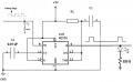
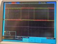
I am trying to get a NE556 to generate a pulse chain based on a square wave input. The circuit is show in the first attachment and the result in the second. No matter what values for R1 and C1 I chose, the result is always the same (i.e., that of the second attachment). The falling edge of the square wave starts the output pulse, which stays asserted until the rising edge of the square wave. According to the NE556 documentation, the length of the pulse should be T = 1.1 * R * C1. I have tried R1 = 100K and C1 = .1 uF, which should yield T = 1.1 * 100,000 * .000001 = 100 mSec. The period of the square wave is about 700 msec (the red trace on the oscilloscope image), so the output should start at the falling edge of the square wave an end 100 milliseconds later. But, the output always stays high until the input goes high.
I don't know what I am doing wrong and would appreciate any help someone can give me.
Attachments
-
 14.7 KB Views: 18
 -
 3.8 MB Views: 16


