Can you identify this component?

Thread Starter

Suck my D(S.M.D. WORK) ;)

Joined May 16, 2024
1
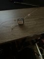
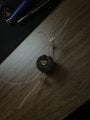
hello, i have been attempting to find out this components use/name for just about a year at this point. I’ve asked quite a few of knowledgeable people. And not a single one has a clue. Nor does google lens, or anything on google. It’s not important, it’s just the fact that I can’t figure it out. So if anyone has some more knowledge then me( not hard) then please, enlighten me. Thanks in advance.
 

Attachments

panic mode

Joined Oct 10, 2011
2,913
well those other people are clearly not as knowledgeable as you thought. besides, electrical components can be treated as a black box and identified. even if the component itself is hidden with just exposed leads.
 

ronsimpson

Joined Oct 7, 2019
3,257
It is made up of two cores like this. The material is P3C8.
Inside there is a plastic bobbin. The wires go around the center many times.
We do not know how the wires are connected so we know little. If I have it in my hand, I could tell you how many turns.
1715892553888.png
1715892838677.png
The one in post #2 is inside a metal can. It could be a transformer for microphone preamplifiers.
 

dovo

Joined Dec 12, 2019
72
The core is called a pot core and can used for all sorts of transformers and inductors. As MrChips says it could be a pulse transformer. I've built pot core pulse transformers. It could be a low power forward converter transformer. Pot cores have high thermal resistance from windings to air and tend to be use at low power. I don't thing it's a flyback transformer or else a plastic screw would be used so as not to bridge (with a metal screw) any air gap between the two halves of the center ferrite center post.

Here is how I would begin to evaluate it:

Using an ohmmeter find out which wires have continuity to other wires.

From that draw it as a transformer or autotransformer whichever the case may be.

Measure the inductance of winding A.

Measure the inductance of winding B.

Measuring winding A, short winding B to find the leakage inductance, or vise versa.

From there it can be driven with a square wave to determine how many volt-seconds it can support before saturation. This will also show its frequency response by the output waveform risetime.


1715893919308.png
 

ThePanMan

Joined Mar 13, 2020
803
I see two wires labeled with a "1" and the other two with a "2". My guess is that it seems to be a transformer. Wires "1" may very well be the primary and the "2's" the secondary. If it were a single inductor with multi-taps there shouldn't be just 1's and 2's.
 

ThePanMan

Joined Mar 13, 2020
803
Find a low voltage transformer, something pushing no more than 12 volts. Lower is better. Start with a known AC voltage and measure what you get on the other end. You'll figure out whether it's a step up or step down transformer and what the ratio is. Been doing some searching, as others probably have, and haven't found anything based on the numbers on your unit.

Measuring the resistance from 1 to 1 and from 2 to 2 will reveal which side has the higher number of windings. That's where you want to push low AC voltage into it. You should be stepping down the voltage.

Still none of us have a clue as to the intended purpose. Just because you can get a different voltage doesn't mean it was designed to do that.

Do you have a need for it? A use for it? Or are you just curious what it is?
 
Top