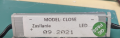
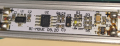
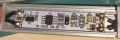
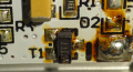
Those drivers and transformers seem to be working fine. he LED broken path could be the cause of the half-working lights, so soldering it back might fix it
U3 is interesting. It looks like it might be a visual sensor, an IR LED emitter paired with an IR receiver that sees when a finger is placed there. The finger reflects the IR back into the sensor. Could that be? Is there a hole in the aluminum case to let light through? Just a hunch - I could be way off.
You might consider another switch. You could use anything from a manual toggle switch to a motion-detector. You might even be able to buy an off-the-shelf capacitance (touch) switch you could put in place of the old one.
Those drivers and transformers seem to be working fine. he LED broken path could be the cause of the half-working lights, so soldering it back might fix it
U3 is interesting. It looks like it might be a visual sensor, an IR LED emitter paired with an IR receiver that sees when a finger is placed there. The finger reflects the IR back into the sensor. Could that be? Is there a hole in the aluminum case to let light through? Just a hunch - I could be way off.
You might consider another switch. You could use anything from a manual toggle switch to a motion-detector. You might even be able to buy an off-the-shelf capacitance (touch) switch you could put in place of the old one.
Yes, it must use IR light or some kind of proximity sensor, it's not a touch button, but a tactile/proximity I think.
These button boards are clicked in a plastic translucent piece glued to the mirror, and I believe there are 2 spots in the mirror that let the sensor light go through, besides letting you know where to put your finger too.
Any way to test which one of those components don't work?
I don't think there's a problem with the hole or spot, since putting the finger close to the broken button makes the LED blink, so it senses the finger, I simply believe the switch is not working. BTW... in the defogger I see a relay that turns it off, but I don't know where's the switch in the LED strip circuit. Is it in the button? U1 or U2?
Also... when you plug the Hot and Neutral, by default, the LEDs are turned on. The 2 button lights are always turned on as well. So the default state is not completely shut off by a main switch or relay.
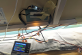
Here's a picture of it. As you can see, LEDs consume 30W, and there is the faulty button. I still don't understand one thing...
See that white box down there?
That's a relay for the defogger, and works fine. However, the LEDs simply appear to have that button only, so I guess the switch must be in that white board, in the same board as the button, right?
I can share a video if you need it, but the button board's LED simply remains ON as you can see, and when you put your finger next to it, the LED blinks rapidly but the strip remains ON forever, so I guess the switch, that I don't know where it is, is not working. Also, the power varies between 30.98 and 32W when you "play" with your finger next to the LED button.
I'm not surprised that the button board needs no relay and can switch the ~250mA directly. On the other hand, perhaps this is why it has failed. I think repairing that board is almost out of the question unless you can find more information on it. Replacing it with an OEM part would be great but I assume that's not possible either. (It's worth a fair amount of hunting to confirm that assumption.) That leaves a hack of some kind.
I'd consider one of those systems they use on faucets at the airport, where you wave your hand past a sensor and it turns the water on for a set period of time. The delay time would be longer of course.
I'm not surprised that the button board needs no relay and can switch the ~250mA directly. On the other hand, perhaps this is why it has failed. I think repairing that board is almost out of the question unless you can find more information on it. Replacing it with an OEM part would be great but I assume that's not possible either. (It's worth a fair amount of hunting to confirm that assumption.) That leaves a hack of some kind.
I'd consider one of those systems they use on faucets at the airport, where you wave your hand past a sensor and it turns the water on for a set period of time. The delay time would be longer of course.
It may well be U2 or U1. My hunch is U1, since I'm guessing that's what was switching the current to the LEDs. Just a guess, though. I think you've ruled out U3 by showing that the LED responds to a finger being detected. You could attempt a shotgun approach and simply replace both U1 and U2 if you can find replacements and you have the soldering chops. Do we know anything about T1? It's another question mark.
One thing I can do, actually, is... remember that I said the this button warms up WAY more than the defogger button?
Which makes no sense as both should not be warm at all. I think I can put some alcohol in the board and see which component is hot. I've seen these rosin fog videos that put some king of fog over a circuit and the faulty component, which can be very hot compared to others, pops up and melts the fog around it. I don't have that fancy thing but I can put some isopropyl alcohol when turned on and see how it reacts.
Wow, guys, check this out... I decided to check which component was heating up so much, so I took my isopropyl alcohol bottle, turned the mirror on, and started to drop it on the PCB to find the component that would evaporate it fast. Turns out it looks like it's totally T1. By the way, wear headphones to also listen to the sound:
MOST electronic component failures do not result in a burn-up. So good visual inspection may find open solder connections, but it will not notice most component failures.
So if the LED strips work, but the switching does not. it may be an actual switch failure. OR a failure of the switch connection.
MOST electronic component failures do not result in a burn-up. So good visual inspection may find open solder connections, but it will not notice most component failures.
So if the LED strips work, but the switching does not. it may be an actual switch failure. OR a failure of the switch connection.
Mostly I see a whole lot of solder flux all over the external connections to that PCB. At the very bottom I see what might be a burn-blob toward the very lower end of T1. So that device may have failed, OR it may be a solder flux bubble.
But I think that I read that the LEDs were switching and that the heater was actually working.
Peeling the wires off of the back of the glass could certainly be a destructive action resulting in non-repairable damage. Many times connections on glass are to weakly bonded metal pads on the surface, that easily peel off.
This mirror appears to have heater wires bonded to the glass, so a repair MIGHT be possible. Maybe.
Mostly I see a whole lot of solder flux all over the external connections to that PCB. At the very bottom I see what might be a burn-blob toward the very lower end of T1. So that device may have failed, OR it may be a solder flux bubble.
But I think that I read that the LEDs were switching and that the heater was actually working.
Peeling the wires off of the back of the glass could certainly be a destructive action resulting in non-repairable damage. Many times connections on glass are to weakly bonded metal pads on the surface, that easily peel off.
This mirror appears to have heater wires bonded to the glass, so a repair MIGHT be possible. Maybe.
I edited the first message... I've fixed all of that, but I am facing the last issue: the tactile/proximity button that powers ON/OFF the LED strip is not working. By default it's ON, so when I connect the mirror to an outlet, the strip turns on, but the thing is I can't turn it off with the button (white PCB). The other button, however, works fine, the one that turns on/off the defogger. Read it again as I explained again the updated situation.
The first step would be to verify that the button itself is actually functioning. By functioning, I mean providing continuity across the contacts when pressed.
Figuring out what T1 is may be tricky. I’d expect a MOSFET (a kind of transistor that is ideal as a switch) but it wouldn’t have to be. And I don’t fully understand how that board works.
I see both sides of the board are labeled with +/-, implying DC input and output. Do you know the supply voltage? I’m just thinking of what specs that transistor might need to meet
Figuring out what T1 is may be tricky. I’d expect a MOSFET (a kind of transistor that is ideal as a switch) but it wouldn’t have to be. And I don’t fully understand how that board works.
I see both sides of the board are labeled with +/-, implying DC input and output. Do you know the supply voltage? I’m just thinking of what specs that transistor might need to meet
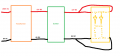
It's 12V DC, you can check the first post, I edited it. Here's the circuit in abstract:
This draw is what I understand by looking at it, may be the LED strip is not exactly like that, I don't know. The first thing that I don't really understand is the 4 cables in the LED strip.
Shouldn't 2 cables just be enough?
Why those 2 extra cables at the end if all are parallel?
May be so if you break the strip once in the middle, it keeps working as it would flow from the other side?
The circuit for the defogger is the same, comes from the same transformer, except you replace the LED strip by a relay that acts a s switch for the defogger, which breaks the 230V AC cable of the defogger. This part works fine.
For this duty the specs of the MOSFET, if that is indeed what T1 is, are nothing special. Almost any that fits physically and is rated to 16V and 1A or more (both to provide plenty of headroom) should work fine.
I’d be tempted to try one and hope for the best. You’d need to sort out the pinout. One pin, source, will be pinned to DC ground. One (drain) will be “hot” and connecting that one to ground should light the LEDs. That’s the job of the MOSFET. You might try that with a power resistor to limit the current to say 20mA. This might light the LEDs dimly but that’s all you need to confirm. The third is the gate pin for the control signal, probably 0V or 12V. Virtually zero current flows here but you should be able to see on your meter when the controller changes the gate voltage.
I don't know if this is relevant, but I just learned the broken LED button it's not simply an ON/OFF button, but it can also dim the light, to make it brighter or darker.
If the button is actually a mechanical switch, then replacement is an option. If it is truly a touch sensor input type device then the problem is not the button, and the diagram in post #37 is very misleading.
Can we get an explanation of how the button is used to select the brightness?
If it is truly a touch sensitive control arrangement then someplace there is a circuit that does more than OFF/ON control. But if it is a mechanical button switch then replacement will be simple.
But from what I can seein the picture of the PCB, the device "U3" is an IR reflective sensor that may be intended to detect touches from behind a clear spot in the mirror. Not at all a touch sensor. So if somehow the assembly had moved from the intended position, the sensor would not be in the location to see the reflected IR light. In that case the problem is mechanical and the solution is putting the sensor back in exactly the correct location.
And the actual button is just a location..
Others need to look at the pictures that show U3 in more detail and see what they can see. I see an LED and a photodiode in U3.
And now, having read that moving a finger makes the LED blink, that has verified that it is the photo sensor. Theelectronic switching transistor, T1, is functional if the LEDs can be switched on.But the current requirement may be excessive.

 Facebook
 Google
 GitHub
 Linkedin