Can UHF Antenna Extension Work Without Electrical Contact?

Thread Starter

Chris _N

Joined Jul 7, 2023
13
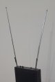
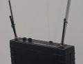
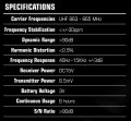
I have a pair of UHF wireless microphones running in the 863-865 MHz band. The default antenna length of the receiver is 8 cm (about 1/4 Wavelength). To get better reception I have made a longer antenna extension of about 40-48 cm by taping to the original antenna. I have tried to make some electrical contact, but as the original antenna is painted I am not sure how much electrical contact there is.

I have 2 questions:
1- Can a UHF antenna extension on the receiver work by induction without making electrical contact by concentrating the RF signal? Or will it only work if it makes direct electrical contact with the original receiver antenna?

2- Is the diameter and weight of the metal of the receiver antenna important? Or is only the length important? In other words, will a thicker and heavier antenna be more efficient than a thinner and lighter antenna of the same length?

Your advice would be appreciated

Kind regards
Chris
 

DickCappels

Joined Aug 21, 2008
10,251
1) only very poorly at best.
2) to maintain desired impedance and hence obtain maximum performance, it is best to stay with the original dimensions.
 

Ya’akov

Joined Jan 27, 2019
9,277
Welcome to AAC.

First, an antenna can operate with some parts being gavancially isolated, that is, not able to conduct DC or low frequency AC.

But, if it is an issue or not you won’t get to the point where it matters because of other problems. Length of an antenna is only important when taken with other features. The two critical aspects of an antenna are resonance, and characteristic impedance.

For an antenna to be resonant, it does have to be a particular length, but that length will be influenced by several factor including the diameter of the conductor(s) used, any conductive materials nearby (including things with a lot of water—like humans) and the shape to name a few.

Resonance makes an antenna far more efficient, but if an antenna is so highly tuned the is has a very narrow bandwidth (we say it has a “high Q”) it will be useful only on one or two channels in a channelized band. So, compromises are usually made to make the antenna more effective across a wider range.

Characteristic impedance is way of describing the resistance of the antenna to power at the frequency of interest. It is less important what the number (measured in Ω) is then that the transmitter’s output stage is matched to the antenna. If it is not, power will reflect from the end of the antenna without being radiated and create standing waves in the antenna and feedline.

The power in these is lost since it will just turn to heat and never be radiated to be received. The metric of interest here is SWR (Standing Wave Ratio) which is the ratio of radiated power vs. the power input to the feedline. An SWR of 1:1 is perfect (and is never really found, though it can be approached).

A slightly mismatched system in terms of antenna length (for example, measured in single digit millimeters for the 800MHz band) can easily bump up the SWR to 2:1 or 3:1, and larger mismatches are certainly easy to create. You can see that even if a matched longer antenna offers better performance in some ways, a longer mismatched antenna is rapidly much worse than a shorter, matched one.

But there are other ways to mismatch an antenna. The antenna impedance is affected by its design—so, for example a ½λ (half wave) dipole antenna has an impedance of 72Ω while a ½λ folded dipole is 300Ω. So, a transmitter designed for a ¼λ whip antenna using an image antenna formed in a counterpoise (the other “half” of the antenna is a virtual one in the grounding of the antenna which for a portable radio is generally pretty bad.) will expect a 50Ω antenna and so anything else will need a matching network to operate properly.

When you lengthen an antenna, you have to change the feedpoint to get a match. Feeding a ½λ whip antenna at the base will not do what you might hope. Another thing is just how a longer antenna is better. They will refer to antenna gain, but how can a passive device have “gain”. It’s not an amplifier!

The gain referred to is gain over an isotropic radiator which in the end means it is gain the same way a flashlight’s reflector makes the beam “brighter”—by restricting the radiation to a particular area. In the case of the gain of an antenna it can be seen in the radiation pattern and may help or harm performance depending on whether the focused energy happens to point to where you need it to go. A directional antenna can degrade performance to exactly the same extent it can improve it.

There is also the regulatory problem. The wireless mic transmitters have to be FCC (or some other country’s regulatory agency) approved. Generally, the approval is done for the entire system which includes the antenna and changing the antenna (on a transmitter) is therefore making it illegal to operate.

So, in the end you are looking in the wrong place to improve performance. The only useful target for tinkering is on the receiver side. You can buy a commercially produced directional antenna, such as a Yagi-Uda array, or a corner reflector and point it at the transmitters. There is no regulatory problem with connecting a new antenna to a reciever, and there is no portability problem since the receiver is in a fixed location.

The manufacturer of the mic system might even offer a directional antenna for the receiver, but if not, you should be able to find one pretty easily.
 

LowQCab

Joined Nov 6, 2012
4,356
You can add series-connected Elements, ( carefully-tuned ),
or,
Reflector / Director Elements, which must also be carefully tuned.

If these additions are not properly tuned,
the overall-performance is likely to be worse than where You started.
.
.
.
 

Thread Starter

Chris _N

Joined Jul 7, 2023
13
Dick, Ya'akov and LowQCab, thank you all for your replies. If I understood your replies correctly, its better for the receiving antenna extension to make electrical contact with the existing antenna, but this will change the optimal impedance. Series connected and reflector elements need to be carefully tuned. The mass and diameter of the antenna might play a role with resonance and tuning but the length is more important.

I can provide some more details.
The receiver is about 4 feet from the floor and cannot be moved any higher. So that is why I need a longer antenna.

I am only interested in making the receiving antenna longer. The low power transmitter is hidden inside the microphones.

The system works well with the original 8 cm antenna (1/4 wavelength) when there are few people in the room. But when the room is full, there are many dropouts and a loss of signal. I guess this is because people are getting in the way of the signal. Also, it is expected that these cheap wireless microphones are more likely to experience problems.

In tests, I fastened a 40 cm antenna (1 1/4 wavelength) to the existing one and this has stopped the dropouts when the room is full. So the bodge antenna extension is actually working, although not as efficiently as the manufacturer intended. I can only conclude that an inferior signal is better than no signal at all.

So, I will try and find a way to make the antenna extension make good electrical contact with the original antenna. I can then experiment with the exact length to see what works best.

Thank you all for your replies. I appreciate your time and experience.

Kind regards
Chris
 

Ya’akov

Joined Jan 27, 2019
9,277
Hello.

I am only interested in making the receiving antenna longer. The low power transmitter is hidden inside the microphones.
That’s great. You can probably do something reasonably λgood on the receiver side

In tests, I fastened a 40 cm antenna (1 1/4 wavelength) to the existing one and this has stopped the dropouts when the room is full. So the bodge antenna extension is actually working, although not as efficiently as the manufacturer intended. I can only conclude that an inferior signal is better than no signal at all.
So, here‘s something you need to take into account. I am certainly not going to argue with the results of your empirical testing—if you saw an improvement then that’s certainly better by definition. If the current improvement was enough you could just leave it at that, but now your challenge is to make it even better, and your successful (by some measures) experiment, unfortunately, doesn’t really provide guidance about what to do next.

So, I will try and find a way to make the antenna extension make good electrical contact with the original antenna. I can then experiment with the exact length to see what works best.
So here’s one of the problems—creating a galvanic connection has as much chance of making things worse as it does of making them better: 50% (that is ignoring the case of no change, which gives us a 33% chance of any one of the three). The reason the odds are so simple is our nearly complete lack of information about what you actually did.

I know you set out to make a “1¼ wave antenna”. The problem is, that’s not a thing—there is no such beast as a (resonant) end fed 1.25λ whip antenna. Practical antennas come in specific relative lengths. The existing ¼λ whip is an example. If you increase the size from there, you start to need matching networks and shifting of the feed point (where the electronics get connected to the antenna).

For example, while the ¼λ whip is end fed, and has a singular radiator, a ½λ whip requires a matching section and the feed point is some distance from the end of the antenna—and so it goes. Your 1¼λ whip is actually a ¼λ end fed whip on the 2m amateur radio band (around 144MHz).

Could you provide the exact make and model of your kit along with some sharp, well lit photos of the antenna connection(s) and what’s you’ve already done? I am sure we can help move in the right direction, but right now we are working blind.

Thank you all for your replies. I appreciate your time and experience.
I am happy to help and I don’t feel it is much risk to say that @DickCappels and @LowQCab feel the same way. WIth a bit more information I am sure we can help make reception more reliable—possibly by means you haven‘t yet considered. In any case, best of luck with your project.
 

Thread Starter

Chris _N

Joined Jul 7, 2023
13
Thank you very much Ya'akov for your reply. I am using a KAM twin wireless microphone set KMA1935. One mic is set to 833 MHz (Channel 1) and the other 835 MHz (Channel 16).

The pictures below show the current setup. I have just tied the antennas together and wrapped copper wire at the base. But the original antenna is painted with black paint, so I am not sure how good the electrical contact is. I can find a way to make better electrical contact by passing the copper wire between the swivel screws on the original antenna.

Kind regards
Chris
 

Attachments

Ya’akov

Joined Jan 27, 2019
9,277
OK, here’s something to try:

Remove the additional antenna parts and connect a ~30cm long wire to the circuit board ground. If there is no exposed ground screw (there sometimes is, somewhere on the case—marked with a ground symbol) you can probably use the ground of the power connection.

I am assuming the power is via a DC supply that plugs in via a barrel or coaxial jack and plug with the negative side of the supply connected to the outside of the plug. You could possibly wrap a wire around the plug (once plus a bit), then plug it in.

The theory is that improving the counterpoise (also called a ground plane) will improve the performance of the existing ¼λ whip by improving the image antenna that it relies on.
 

Thread Starter

Chris _N

Joined Jul 7, 2023
13
OK, here’s something to try:

Remove the additional antenna parts and connect a ~30cm long wire to the circuit board ground. If there is no exposed ground screw (there sometimes is, somewhere on the case—marked with a ground symbol) you can probably use the ground of the power connection.

I am assuming the power is via a DC supply that plugs in via a barrel or coaxial jack and plug with the negative side of the supply connected to the outside of the plug. You could possibly wrap a wire around the plug (once plus a bit), then plug it in.

The theory is that improving the counterpoise (also called a ground plane) will improve the performance of the existing ¼λ whip by improving the image antenna that it relies on.

Thank you for this suggestion Ya'akov. Should the 30 cm wire connected to earth hang down or up or in any special orientation?

Kind regards
Chris
 

Ya’akov

Joined Jan 27, 2019
9,277
Thank you for this suggestion Ya'akov. Should the 30 cm wire connected to earth hang down or up or in any special orientation?

Kind regards
Chris
Four, shorter stiff radials at 90° intervals pointing down at a 45° angle is ideal, but one longer one at parallel to the ground or. hanging straight down is a good test.
 

LowQCab

Joined Nov 6, 2012
4,356
Without knowing the actual physical-environment,
the best solution is hard to say.

I am "assuming" that You have a Table setup for mixing,
and that it is in the back of the room,
and that the reason You can't get higher than ~4-feet is because
that is the highest piece of equipment that You have stacked-up on your table
that You can place the receiver on top of.

If this is the case, I would suggest that You put-on your creative-solution-hat and
figure-out a way to mount the Receiver upside-down to the ceiling,
or at least, somehow, get the entire Receiver, plus Antennas, above the heads of the crowd.
Then, no Antenna monkey-business will be required.

There's nothing particularly "wrong" or "cheap" about your Wireless-Mic setup.
Lots of bodies can easily absorb the tiny amount of RF-radiation from the Mic Transmitter.

This is just one of the many reasons why the Mixer-setup is normally on a raised-platform.
.
.
.
 

Thread Starter

Chris _N

Joined Jul 7, 2023
13
Without knowing the actual physical-environment,
the best solution is hard to say.

I am "assuming" that You have a Table setup for mixing,
and that it is in the back of the room,
and that the reason You can't get higher than ~4-feet is because
that is the highest piece of equipment that You have stacked-up on your table
that You can place the receiver on top of.

If this is the case, I would suggest that You put-on your creative-solution-hat and
figure-out a way to mount the Receiver upside-down to the ceiling,
or at least, somehow, get the entire Receiver, plus Antennas, above the heads of the crowd.
Then, no Antenna monkey-business will be required.

There's nothing particularly "wrong" or "cheap" about your Wireless-Mic setup.
Lots of bodies can easily absorb the tiny amount of RF-radiation from the Mic Transmitter.

This is just one of the many reasons why the Mixer-setup is normally on a raised-platform.
Thank you very much for your advice. I appreciate all the suggestions I have received. I will consider all the options and try to find the best solution.

Kind regards
Chris
 
Top