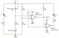
This circuit outputs LOW on D when a magnets passes by the reed switch. Can it be converted to output HIGH instead? (HIGH being 3.3V, the voltage at which I'm powering the circuit).
INDEED!! exchanging the opamp inputs should reverse the operation. BUT also, changing the reference voltage on pin #3 is not likely to work because with the reed switch open pin #2 is very close to Vcc.
That depends on how much, if any, parts of the circuit as shown can be modified. If the connections to the IC pins #5 and #6 were exchanged, then the function will be reversed, without any other changes.
OR, the LED and resistor could be moved to connected between pin#4 and the common. That will reverse the function of the LED but not change anything else.
I can lift the legs #5 and #6 of the LM393 and re-route the connections...
However, what about connecting the gate of an AO3400 N-Channel mosfet to D, the source to ground, the drain to VCC using a 10K resistor and use the voltage level measured from drain to ground and output? I'd like to trigger at interrupt on a microcontroller that expects 3.3V logic, in this case a HIGH signail.
That would work also. BUt the request in post #1 was to modify, not add parts. If the circuit is on a PCB then it does get a bit more tedious, but cutting runners and adding jumpers can certainly be done.
that should be clear once the actual part number of the sensor is known. it may not be really a "reed switch". perhaps it has significant leakage current or response is a curve that is not very steep...
J999, you shoould be aware by now that half the time somebody has already decided where the problem is, and is asking for a fix, when the problem is someplace not in the part we are shown. There are many types of sensors that simply change resistance in response to some physical change, but they do not have a standard symbol. The best I have seen tor those was "Thing #1" and "Thing #2" on a drawing done for me. I told the detailer who did the drawing that was perfect, until I could discover the proper symbol.
To be clear, an LM393 is not something that is "as-comparator". The 393 *is* a comparator, not an opamp. It does not have a full totem-pole output stage and is not internally compensated, so when used as a linear amplifier it might break into oscillation in some circuits. The"OPAMP" label on the schematic is incorrect.
Separate from that - According to the schematic, output D will go high when a magnet passes the switch. This assessment assumes that the "Reed Switch" impedance changes from a high value to a low value when a magnet is parked over it.
RIGHT! AND, unlike an OP-AMP, the LM393 COMPARATOR requires a pull-up resistor because it has an NPN open collector output.
I accidentally overlooked that in responding to some post that had a 393 driving an LED.
It was an error I made on another thread, then. It had an LM393 lighting an LED tied to the output with a series resistor to V+, which works. But they wanted to revers the sense of the LED, With an op-amp used as a comparator that would be simple, just put the LED and resistor between output and common instead of between output and V+. With an NPN open collector output it is a bit more complicated. And much less efficient.
 Facebook
 Google
 GitHub
 Linkedin
 80.5 KB Views: 43


