hi thor,
That is a powerful PSU, have you calculated the total power requirement for the complete house installation?
Post a rough sketch showing the installation.
E
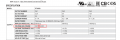
Clip: PT-6503 AC-DC Triple output Open frame power supply; Output 3.3Vdc at 7A +5Vdc at 10A +12Vdc at 1.2A
1A for 12V channel (trying to figure out for what it can be used)
I am amazed at the level of concern about the voltage difference between a3.3 volt supply and a "3 volt battery" supply. Certainly for the AA and AAA battery applications there is no issue at all, because the voltage of most available dry cells starts out at over 1.50 volts, often more like 1.65 volts, or even a bit more for fresh cells of some brands. Likewise for the coin cells, which BTW, I have seldom seen used in parallel, except where two holders are arranged to allow replacement without losing memory retaining voltage while changing batteries.
Consider that battery voltages are not constant other than for very short time periods.
Some of the projects using the microcontrollers require more precision and less noise. What about voltage tolerances, look closer.
In some cases the decision to use a Voltage regulator for it's noise reduction can be made using simulation. Low cost, not easy, but I'll try.
Even the greatest power supplies may not help, so then what? Batteries, and along with batteries the low voltage.
Regulator data sheets, Which Lipo batteries will remain low cost and plentiful, which topology has been working ok. Many Vregulators.
Taking a battery approach and using only a data sheet is still trial and error. Take a chance, listen to experience.
Take a look at the block diagram in pdf below, it shows the topology. Is it that our effort just is'nt good enough? (they meanwell)
A simulator may not have the model but collectively there might be a solution. I think noise approach may help even in the best battery supply 2.80 - 3.20 V but fixed within that range and not drifting as batteries do. The 100 ppm looks ok in the chart
What caught my eye was suitable use description available in a 1% 3.00V but using recommended caps looks like 2.9V on the chart 200mA
p.8 Output voltage vs input, xc6206P302 suggest that a 4V or higher down to 3.2 V will give longer run time referring to 40mA for this regulator.
a lot of possibilities again which one charges and is low noise may need factory trimmed 8.5 5.0 3.3 that will accept a 3.0 regulator. 100mV increments.
i have bunch of smarthome devices as amazon blink cameras (5v) , aqara motion sensors, hue motion sensors (3V)
I plan house reconstruction so i was thinking to have separate lines in the wall for 3V and 5V - so i can attach these battery powered devices to that.
.....
you are not going to have the entire bunch sitting all in one place, next to PSU... so you are going to run some wires. and they will be of varying length. combined with variable current draw of all devices, voltage drops to each of them are of course going to be different. so if you are concerned about 0.3V difference, using single central 3V PSU is a wrong approach.
it would be better to use higher voltage supply and have regulator at each device.
today wireless is everywhere but there are problems - including security, so hard-wire is still a king...
but... do not get locked in... tomorrow you may not like what you have as new crop of products completely outshines the old ones.
so if you are remodeling home and have access, the most flexible solution is to install PVC tubes rather than cables. cables are one time deal unless you plan on demolishing walls again. but tubes are forever. with tubes, you can still easily replace whatever is in there and pull in whatever the technology of the day is... coax cable, phone wiring, fancy shmancy multi conductor cable, Ethernet cable of whatever current standard is (Ca5/6/7/8/9), fiber optic or anything else...
form factor is different - one is open frame and needs housing, the other is sealed unit, meant to be portable.
the rating is different - one can handle much more current than the other
the flexibility is different - one can be adjusted and the other cannot
the approvals are different - one is built to meet industrial standards of the world... including CSA, UL, etc, the other only has CE (or does it? it may be just faked)
the testing is different - one has been subjected to a factory burn-in test and test details/specs are clearly listed. the other has no mention of any tests or standards. it is even unclear what the output voltage tolerance is (may be labeled 3V but... the actual voltage could be 2.7V or 3.5V... or something else). and there is no mention of ripple, noise or anything else...
you are not going to have the entire bunch sitting all in one place, next to PSU... so you are going to run some wires. and they will be of varying length. combined with variable current draw of all devices, voltage drops to each of them are of course going to be different. so if you are concerned about 0.3V difference, using single central 3V PSU is a wrong approach.
You are absolutely right, so that's why am I still not sure.... Does it mean it safe and it won't pose any issues? Assuming some devices from psu will be by cable easily 5-10m away. Is all of that okay?
Yeah, but is there a solution for that, how and where to install these tubes?
That's my concern also bc as you mentioned once device is replaced or change location it's issue.
I was thinking to have 3v, 5v, 12/24 for led lights wires across the whole house. But this is 6-8 wires per each voltage.
So maybe its better to have let's say one circuit 24V or two circuits and use controllers for each endpoint device. In such a case it's 2-4 wires compare to 8.
The issue will be desing of the PSU, as it's hard to guess MAX W of it.
Regarding these endpoint regulators, is it safe and good idea? Is it possible to reccomend brand that is producing these regulators? Something good as mean well for PSU.
But still not sure if that's something people normally do or it's just my insane design - which might be at the end nonsense / pointless.
Faced with that problem I would run only 5V and use a 3V regulator for each 3V device. Then you need only a single 5V supply (which are cheap), and half the wiring saving you a bit of money.
Faced with that problem I would run only 5V and use a 3V regulator for each 3V device. Then you need only a single 5V supply (which are cheap), and half the wiring saving you a bit of money.
the more load you plan on, the more sense it makes to use higher voltage... 24V supplies are common and can deliver more power over same wires. and one can easily step voltage down individually for each node using DCDC converters. some are really small

 Facebook
 Google
 GitHub
 Linkedin


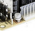


 the cheap black blastic box.





