Can a reflector be used with an 11 meter dipole antenna to boost performance?

Thread Starter

Darkstar

Joined Sep 3, 2010
182
The Loop Antenna does not have to be exactly square.
It can be 8 X 10 without much noticeable difference in performance or tuning.
Think of it as 2 Di-Poles, slightly further apart than 1/4 WL,
with 6- inches of the top tip, and bottom tip, bent at a 90 degree angle,
this is only a small percentage of the overall Radiating Element,
add to this, that the Current that flows at the tips of these 2 Di-poles is quite low,
and goes to almost zero by the time you get half way between the Vertical Legs.

To give you an idea of how squishy Antennas can be,
a perfect Circle works just as good as a Square,
and a Triangle is not far behind,
which seems to defy the accepted, basic explanation, about how a Loop Antenna works,
and to top-off all that, when you get into lower frequencies,
how far you are above the ground, (measured in Wavelengths),
starts having a serious effect on how the Antenna performs, (or not),
it also affects SWR, Impedance, and Radiation Patterns,
which is why Hams ALWAYS have some sort of Match-Box,
not only are they trying to cover a huge frequency range with one Antenna,
the antenna is almost always too small compared to a Wavelength,
and too close to the Ground compared to a Wavelength,
so, the fact that they get the damn thing to work at all is a miracle.

On the other hand .........
When working with CB Frequencies, you are much better off accomplishing all of your
Antenna Tuning by making physical adjustments to the Antenna its self until you get
an acceptable level of Resonance, ( SWR and Impedance), along with an acceptable Radiation Pattern.
When you make these Tuning changes directly to the Antenna or the Coax,
instead of seeing if you can get it to work with a Match Box,
you wind-up with a far more elegant, efficient, simple, and generally higher performance, "System".
A Match Box can make a Chain-Link Fence work as an Antenna,
its performance will be very poor, but you can probably achieve an almost perfect SWR.
When a properly Tuned Antenna is used, there is zero need for a Match Box to "Fix" things.
A Match Box will always introduce its own losses, even when used with a perfect Antenna,
and the further out of Tune the Antenna is, the more losses the Match Box introduces into the mix.

Ideally, you want the Antenna to "act like" a 50-Ohm Resistor, (which is never gonna happen).
If the Antenna is "short" it will act like a Capacitor,
if the Antenna is too "long" it will act like an Inductor.
The Antenna is trying to simulate a Resistor using a specific balance of Inductance and Capacitance,
this is specifically why the Antenna is said to have "Impedance" rather than "Resistance".
Actually, the DC-Resistance on many Antennas is almost zero Ohms, or a direct "Short",
but the "Impedance" may be ~700 Ohms, or even "infinite", at a certain High-Frequency range.

The "Impedance" is what you are tweaking with a Match Box,
this is done by adding or subtracting Capacitance, and/or, Inductance,
both in Series with, and/or, in Parallel with, the Antenna.

The ideal Impedance can be achieved by simply altering the "Length" of the Antenna by a small amount,
or altering the length of the Coax, which should only be "the back-up plan",
and only resorted to after all Antenna adjustments have been tried,
but you still have some minor SWR issues that you would like to minimize.

Having to "add" some kind of Tweaking Device to the Antenna to get it to work,
is a sure indicator that the Antenna is poorly matched to the Frequency that you are using.
The only time that this is an acceptable solution is when you only have practical space for one Antenna,
but you are working with a wide range of different Frequencies.
This is why Hams use Match Boxes,
which are actually a liability when using only a narrow Frequency Range.

BTW, that 1979 CB Radio is not what I had in mind when I said "Modern".
Capacitors, especially cheap ones, and/or, older designs, have a finite life expectancy,
same goes for most of the other components.
I was referring to "Complete-Radio-on-a-Chip" type of Modern,
something that is extremely stable, and reliable,
with designed in protection features so you can't smoke it if something goes wrong.
Just like with your old Tube CB Transceiver, it's a miracle that it actually still functions with no smoke.

But I would like to add that .......
Tube Gear is easily tweakable, and when it is in good working order,
"CAN" have superior modulation characteristics,
that doesn't mean that it automatically does though,
just that they are usually easy to tweak to easily deliver ~125% modulation of the "Positive-Peaks".
Most transistorized CB Radios have very limited modulation of the "Positive-Peaks",
where the nominal ~4-Watts of RF output power "should" temporarily go to ~8-Watts or more.

( only over modulation of the "Negative-Peaks" causes unwanted interference on adjacent channels)
.
.
It's never going to be perfect, but it's the best I've had all year and it will get better as I check the radial lengths after soldering new sections to them. In the spring I can have the antenna indoors but the tip of the wire outside and the radials can spread on the balcony. If I can find a way to easily put them through an insulated gap in the open sliding door I can do it now. I already have a couple ideas in mind which would work well.

You always hear about 102'' to 108'' 1/4 wave whips. Earlier this year I tried a 1/4 wave gnd plane ant, which originally came with 102'' vertical and radials but in the house I had it horizontal with six 102'' wires as horizontal radials. I kept adding length to the 'vertical' until the SWR was similar to what I got with the 50 ohm dummy ant. The SWR bottomed out when the ant was 120.5''. Did it twice w same results. Again, I didn't know why, but that's what it liked. Was there too much capacitance from nearby objects thus the ant wanted to be longer and more inductive? Or, 120'' + 102'' (radials) = 222''. Maybe it was trying to work as a dipole, each half would be 111'' long which is near 108''. ??

With this current ant, the first tuning with 1/4 wave radials seemed to prefer everything to be ~104''. Time will tell how the next round of tweaking with the 1/2 wave radials will turn out.
 

Thread Starter

Darkstar

Joined Sep 3, 2010
182
At the bare minimum, set the transmit channel to mid-band or to the channel you will be using the most. With a good SWR meter (not the one on the radio) observe the reading while transmitting and add or subtract wire to the antenna to bring it as close to 1:1 as you can. I assume you are using a balun to connect the 50Ω impedance transmitter output to the antenna. In the end though, all you will have is access to the CB airwaves and all that entails. Which is pretty dismal...
Ok, dumb question here, I hear of baluns being used sometimes and sometimes not. I can understand if you are using 50 ohm coax to connect to a folded dipole made of 450 ohm twin lead or anything along those lines. But why would I need a balun connecting coax to a gnd plane ant when all parts of the system are 'supposed' to be made for 50 ohm impedance? What is the benefit? Thanks.
 

SamR

Joined Mar 19, 2019
5,542
Balun - Balanced to Unbalanced matching device. The output impedance of a transmitter is typically 50Ω impedance and the antenna is ??? well it's pretty much undefined. This is why a Balun is used. It gives you maximum power transfer from the transmitter to the antenna. Baluns: Choosing the Correct Balun (dxengineering.com)
Most Baluns are manufactured for Ham rigs which are typically 100W transmitters with amplifiers. So they are built for a couple of kW of power. There is lots of info on homebrew Baluns for QRP (5W or less) rigs which would be easy enough to do using a toroid form and wire.
 

LowQCab

Joined Nov 6, 2012
5,102
Any Antenna will have a "Distributed-Impedance",
so, the Impedance depends on where the Feed-Line attaches to the Antenna.
there will usually be 1 or 2 spots where the Impedance is the lowest, this spot will also have the lowest Voltage,
and 1 or 2 spots were the Impedance is very high, this is also where the Voltage is the Highest.
Volts X Amps = Watts, and the Wattage is the same throughout the Antenna,
but, oddly enough, the highest concentration of Current is were the highest RF Radiation is generated.
Generally speaking, a standard Di-Pole has the highest Current, and lowest Voltage, right in the center,
But you can take this Antenna and "End-Feed" it.
This requires very high Voltage, but very little Current,
which is where a Transformer comes in.
This is exactly the job that Transformers were designed to do,
"transform" Current into Voltage, or, Voltage into Current.
Using this principle, you can even "Top-Feed" a 1/4 Wave Vertical Ground Plane Antenna,
where it will probably have around a ~300-Ohm Impedance, and very high Voltages.
This is also directly related to the reason that "Open-Ended" Antennas are
"noisier" when used for Receiving, as opposed to a "Closed-Loop" Antenna.

However, anything that you put between your Rig and your Antenna
is going to cause "some" loss of Efficiency, maybe a lot,
and create additional Tuning challenges,
this includes the Coax Cable.

So, if you can arrange things so that you can connect your Coax directly to the Antenna,
in a spot on the Antenna that is exactly ~50-Ohms, it's all-good,
and the most efficient way of transferring Power from your Radio to the Antenna without directly
mounting the Antenna to the back of the Radio.
( Actually, Open, Twisted, "Ladder-Line" is more efficient than Coax, just no where near as convenient ).
Then, all you have to be concerned with is the Radiating Efficiency of the Antenna,
and in which general Directional-Pattern the Antenna will attempt to send that Power.

The simpler you can make it, the better it works.

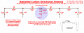
Notice in this picture how the "Feed-Point" determines the Impedance "seen" by the Coax .......
.
. Bobtail Curtain 1 Flat .png
 

Thread Starter

Darkstar

Joined Sep 3, 2010
182
Sam and Low,
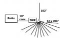
I've taken your advice and removed both the match box and the excess coax between radio and antenna. It wasn't necessary since they are next to each other. When I had the long coax inline between radio and antenna I did have what they call 'ugly' baluns on each end (5 turns of coax, ~4.5'' diam, air core). Now the radio connects to the SWR meter with about 18'' of coax. The SWR meter connects directly to the antenna base.
Without choke.jpg
My output signal was strong according to the radio meter (not accurate, I know) and the separate field strength meter (which is only relative.).
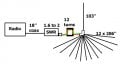
Then I tuned the 1/4 wave gnd plane made last week for low SWR. It tuned to 1.5. Then I tried inserting a 1:1 common mode choke between the SWR meter and antenna.
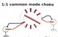
With choke.jpgThe SWR jumped to 3 and my radiated signal strength dropped. More tuning got the SWR between 1.5 and 2 and got most of the radiated signal back. I used the following winding on a square torroid using 12 turns:
1 to 1 common mode choke.jpgI put an AM FM radio next to the transceiver and found there was less interference with the choke in place but I seemed to be radiating less. I resolved most of the problem so I didn't pursue this.
Next I will remove the choke and insert this 1:1, 50 ohm balun in its place & see what it changes:
I tried something close to this.jpg After I get the parts made and can swap them around without altering the relative positions of antenna and field strength meter I'll be able to get some idea how much the signal gets attenuated by the choke and balun.
 

LowQCab

Joined Nov 6, 2012
5,102
Well, I suppose if you find that sort of thing interesting ........
To each his own.
I'd throw-out the Baluns/Chokes/Tuners/etc.,
and concentrate on designing an Antenna that works efficiently without all that extra stuff.
If you were a Ham trying to talk on widely varying Frequencies, that's a different challenge.

Back in the '70's, I was a lucky kid in that my Dad took an interest in my pursuit of
building a Base Antenna for CB.
He was able to get 5- 10-foot pieces of 1/4 inch S-S tubing from his workplace,
which we cut down to ~9 feet.
( I didn't know what Velocity-Factor meant at the time )
Then, using a 10 inch piece of ~1.5 inch dia. Phenolic material, (aka Rag-Board),
with 5 holes drilled near one end, made a 1/4 Wave Ground Plane Antenna,
with the stripped ends of the Coax attached to the Elements with small Hose-Clamps.

This Antenna would reliably cover a ~5 mile radius during the day, and ~20-plus-miles + Skip, at night.
If I could hear them, they could hear me,
( except for the few crazy guys running ~500 or ~1000 Watt Linear Amplifiers attached to
3-element Quad Beam Antennas on a 50 foot Mast ).
This was with the Antenna only ~13 feet off the ground,
and surrounded by ~20 or so massive Pine Trees,
and a used piece of junk Midland Mobile CB Radio,
with a 12V Power Supply made from scavenged junk-box parts.
I couldn't afford a proper SWR Meter,
and never found out what the SWR might have been.
There was nothing but ~25 feet of cheap Radio-Shack Coax between the Radio and Antenna,
and there was no way to "tune" anything, and none was needed.

This was not an accident,
I read every book and magazine article I could find on designing Antennas,
and concluded that it was actually pretty simple, and it turned out that it was.
Just follow all of the General Rules as closely as you can, and it will work.
.
.
 

Thread Starter

Darkstar

Joined Sep 3, 2010
182
Well, I suppose if you find that sort of thing interesting ........
To each his own.
I'd throw-out the Baluns/Chokes/Tuners/etc.,
and concentrate on designing an Antenna that works efficiently without all that extra stuff.
If you were a Ham trying to talk on widely varying Frequencies, that's a different challenge.

Back in the '70's, I was a lucky kid in that my Dad took an interest in my pursuit of
building a Base Antenna for CB.
He was able to get 5- 10-foot pieces of 1/4 inch S-S tubing from his workplace,
which we cut down to ~9 feet.
( I didn't know what Velocity-Factor meant at the time )
Then, using a 10 inch piece of ~1.5 inch dia. Phenolic material, (aka Rag-Board),
with 5 holes drilled near one end, made a 1/4 Wave Ground Plane Antenna,
with the stripped ends of the Coax attached to the Elements with small Hose-Clamps.

This Antenna would reliably cover a ~5 mile radius during the day, and ~20-plus-miles + Skip, at night.
If I could hear them, they could hear me,
( except for the few crazy guys running ~500 or ~1000 Watt Linear Amplifiers attached to
3-element Quad Beam Antennas on a 50 foot Mast ).
This was with the Antenna only ~13 feet off the ground,
and surrounded by ~20 or so massive Pine Trees,
and a used piece of junk Midland Mobile CB Radio,
with a 12V Power Supply made from scavenged junk-box parts.
I couldn't afford a proper SWR Meter,
and never found out what the SWR might have been.
There was nothing but ~25 feet of cheap Radio-Shack Coax between the Radio and Antenna,
and there was no way to "tune" anything, and none was needed.

This was not an accident,
I read every book and magazine article I could find on designing Antennas,
and concluded that it was actually pretty simple, and it turned out that it was.
Just follow all of the General Rules as closely as you can, and it will work.
.
.
I hadn't planned to include a balun but Sam thought I needed it so I thought I'd see what effect it had. I thought it would bring the SWR down but it went up. I don't understand how the balun is supposed to mate the antenna to the rest of the line when I don't know what the antenna impedance is? I don't know what I'm balancing because parts are made for 50 ohms and the lopsided antenna is anybody's guess. That's why the adjustable tuner makes sense. I think when I first connected the antenna directly to the SWR meter I had a huge signal but the SWR was over 3 and it was easily picked up on the AMFM radio. From what I've seen, a very high apparent output at a high SWR seems to mean something isn't matched and so is radiating where it shouldn't be. Right now I have the best antenna I can fit indoors. It's tuned for an SWR of 1.5 to 2 across all channels without using the tuner. According to the little power meter on the radio, without the balun or choke it read 4 but with either it reads only 2.5. I have yet to make a true relative comparison. I'll have to fiddle with it more to see what does or does not help. I still plan to try the loop antenna you suggested. That appears to have fewer areas to make adjustments so if the SWR is too high I'll just have to use the tuner.

This is the best antenna I've made all year, maybe now I won't go for weeks on end not hearing a single thing. I don't know my max distance, but I do know I'm getting at least a mile. I've heard people saying they were in Chicago, Washington state, & (I think) Vermont.
Thanks for your help.
 

SamR

Joined Mar 19, 2019
5,542
Baluns are a bit of a Black Art... Your radio's output impedance is typically 50Ω. Measuring the antenna's impedance @ the transmit frequency is why the Network/Antenna Analyzers are so popular.
 

LowQCab

Joined Nov 6, 2012
5,102
Sitting "inside" the Antenna will cause all sorts of wacky effects, GUARANTEED.

The Power Meter on the front of your Radio is just "visual-entertainment" it actually shows
nothing meaningful, except maybe that your Radio appears to be functioning, and that's IT.
But, the "S-Meter Function" while receiving,
can be somewhat useful for "relative comparisons" of the strength of received signals,
but even this can vary wildly depending upon Weather-Conditions and the Time-of-Day.

The proximity of your Physical Body to the Antenna
WILL have a profound effect on the performance of the Antenna.
Exactly what that effect might be is anyone's guess, but you can bet that it won't be good.
This effect is much more pronounced with "Open-Ended" Element Antennas,
as compared to a Closed, or "Loop" type of Antenna.
The Radio its self, will NOT like having all that RF blasting around the room,
and again, it's anyone's guess as to how it might react.
Here again, a Loop Antenna is "less-likely" to cause RF feedback into the Radio or Microphone.

When SWR ( Reflected RF ), is high,
there is a much better chance of having RF running on the OUTSIDE of the Coax.
This is always a bad thing, and if you just really really want to put something in between your
Radio and Antenna, it would be a "Snap-Around" Ferrite RF Choke, placed right at the Antenna.
You can have as many as you want, but the first one is the most important one.
These are available from any Electronics Supplier, and most larger Computer Supply/Repair Shops.

The Coax should always be routed 90 degrees from the designed Polarization of the Antenna.
In other words, if it's a Vertically-Polarized Antenna, the Coax should be routed horizontally away
from the Antenna Feed-Point.
If it's a Horizontally-Polarized Antenna, the Coax should be routed Vertically downward from the Feed-Point.
Many times this is not really practical, and this one of those times when an RF Choke snapped around
the Coax can lessen any negative effects from the Coax being in close proximity to the Antenna.
Remember that the OUTSIDE of the Coax acts just like an Antenna that is running very close
to your Main Antenna, and will have RF induced into it, which will be routed directly back to your Radio.
These are the most important reasons to keep SWR low,
NOT loss of Power, or overheating your Radio's Final-Output-Stage.

When you are operating on a rather narrow Range of Frequencies, such as CB,
there is absolutely no need for any type of Antenna Tuning device.
A Match-Box won't "fix" a poor Antenna design.
The only reason you should NOT have a very low SWR, is because your Antenna is NOT tuned to
the frequency range that you are using.
So, TUNE THE ANTENNA,
don't install a "Fix-in-a-Box" in your Coax run in between your Radio and Antenna.
Every time you "add" something to "fix" something else, you just make things more complicated.
( with the exception of the Snap-On Chokes mentioned earlier, they generally don't cause any problems )

If you take the exact length of a Wavelength,
and multiply it by the estimated Velocity Factor of the Elements you are using,
then cut all of the Elements to that exact length,
then lay-out the Elements in a known to work Pattern,
you will very likely wind-up with a working Antenna with an SWR under 3,
it's really that easy, just figure out which one of these things you are NOT doing, and FIX THAT.
If the SWR is under 3 don't mess with it,
if it's under 2 you're a lucky man,
if it's near 1, it's almost like a miracle from God.

Tuning an Antenna ..........
After you have done everything within your power to create a near-perfect Antenna.
( Read the First Line 3 more times ......)
And, you want to tune it to achieve that particular Antenna Design's maximum performance,
positioned in that particular location .........

1) Install your SWR Meter as close to the Antenna Feed-Point as you can physically get it.
This will create the most accurate readings.
2) Test SWR on Channel "1", write it down.
3) Test SWR on your Highest Channel ( 23 or 40 ), write it down.

4) Compare the 2 numbers,
4a) If Channel 1 has a higher SWR than Channel 23 (40), then the Antenna Elements are too short.
4b) If Channel 1 has a lower SWR than Channel 23 (40), then the Antenna Elements are too long.

5) Cut, or lengthen, the Antenna Elements until the SWR is roughly equal on each end of the Tuning Band.
This procedure will give you the lowest practical SWR reading in the Center of the CB Band.

This is the only time, and the only way, that an SWR Meter should be used with a CB Rig,
unless something happens to physically alter the Antenna, or its Location, or surrounding objects.

This does NOT mean that you now have an efficient Antenna,
and/or,
an Antenna with a desirable Radiation Pattern.
.
.
 

Thread Starter

Darkstar

Joined Sep 3, 2010
182
Sitting "inside" the Antenna will cause all sorts of wacky effects, GUARANTEED.

The Power Meter on the front of your Radio is just "visual-entertainment" it actually shows
nothing meaningful, except maybe that your Radio appears to be functioning, and that's IT.
But, the "S-Meter Function" while receiving,
can be somewhat useful for "relative comparisons" of the strength of received signals,
but even this can vary wildly depending upon Weather-Conditions and the Time-of-Day.

The proximity of your Physical Body to the Antenna
WILL have a profound effect on the performance of the Antenna.
Exactly what that effect might be is anyone's guess, but you can bet that it won't be good.
This effect is much more pronounced with "Open-Ended" Element Antennas,
as compared to a Closed, or "Loop" type of Antenna.
The Radio its self, will NOT like having all that RF blasting around the room,
and again, it's anyone's guess as to how it might react.
Here again, a Loop Antenna is "less-likely" to cause RF feedback into the Radio or Microphone.

When SWR ( Reflected RF ), is high,
there is a much better chance of having RF running on the OUTSIDE of the Coax.
This is always a bad thing, and if you just really really want to put something in between your
Radio and Antenna, it would be a "Snap-Around" Ferrite RF Choke, placed right at the Antenna.
You can have as many as you want, but the first one is the most important one.
These are available from any Electronics Supplier, and most larger Computer Supply/Repair Shops.

The Coax should always be routed 90 degrees from the designed Polarization of the Antenna.
In other words, if it's a Vertically-Polarized Antenna, the Coax should be routed horizontally away
from the Antenna Feed-Point.
If it's a Horizontally-Polarized Antenna, the Coax should be routed Vertically downward from the Feed-Point.
Many times this is not really practical, and this one of those times when an RF Choke snapped around
the Coax can lessen any negative effects from the Coax being in close proximity to the Antenna.
Remember that the OUTSIDE of the Coax acts just like an Antenna that is running very close
to your Main Antenna, and will have RF induced into it, which will be routed directly back to your Radio.
These are the most important reasons to keep SWR low,
NOT loss of Power, or overheating your Radio's Final-Output-Stage.

When you are operating on a rather narrow Range of Frequencies, such as CB,
there is absolutely no need for any type of Antenna Tuning device.
A Match-Box won't "fix" a poor Antenna design.
The only reason you should NOT have a very low SWR, is because your Antenna is NOT tuned to
the frequency range that you are using.
So, TUNE THE ANTENNA,
don't install a "Fix-in-a-Box" in your Coax run in between your Radio and Antenna.
Every time you "add" something to "fix" something else, you just make things more complicated.
( with the exception of the Snap-On Chokes mentioned earlier, they generally don't cause any problems )

If you take the exact length of a Wavelength,
and multiply it by the estimated Velocity Factor of the Elements you are using,
then cut all of the Elements to that exact length,
then lay-out the Elements in a known to work Pattern,
you will very likely wind-up with a working Antenna with an SWR under 3,
it's really that easy, just figure out which one of these things you are NOT doing, and FIX THAT.
If the SWR is under 3 don't mess with it,
if it's under 2 you're a lucky man,
if it's near 1, it's almost like a miracle from God.

Tuning an Antenna ..........
After you have done everything within your power to create a near-perfect Antenna.
( Read the First Line 3 more times ......)
And, you want to tune it to achieve that particular Antenna Design's maximum performance,
positioned in that particular location .........

1) Install your SWR Meter as close to the Antenna Feed-Point as you can physically get it.
This will create the most accurate readings.
2) Test SWR on Channel "1", write it down.
3) Test SWR on your Highest Channel ( 23 or 40 ), write it down.

4) Compare the 2 numbers,
4a) If Channel 1 has a higher SWR than Channel 23 (40), then the Antenna Elements are too short.
4b) If Channel 1 has a lower SWR than Channel 23 (40), then the Antenna Elements are too long.

5) Cut, or lengthen, the Antenna Elements until the SWR is roughly equal on each end of the Tuning Band.
This procedure will give you the lowest practical SWR reading in the Center of the CB Band.

This is the only time, and the only way, that an SWR Meter should be used with a CB Rig,
unless something happens to physically alter the Antenna, or its Location, or surrounding objects.

This does NOT mean that you now have an efficient Antenna,
and/or,
an Antenna with a desirable Radiation Pattern.
.
.
I realize being inside the antenna near metal objects and sitting on the radials is not optimal.
Today I took readings for over 60 different ways to connect the components from having nothing in the line but radio directly connected to SWR meter to short coax to the antenna up to having these items plus the balun and tuner and one extra short cable because space was tight to make a direct connection. The results are mostly all over the place, but a quick summary shows I got the lowest SWR, highest radiation, and "normal range" readings from the meter on the radio when everything was in the line. I didn't want to bore you with the details, but if you want to see the numbers I'll post them. I've highlighted especially good and bad results. That's as far as I've gotten so far.

I know the little radio meter is not accurate, but I know what I've always seen it read so if it says over 4 or under 2 that's unusual. I got one reading under 1! The S meter, for me, is the more useless one. My bkg noise level ranges from 1/4 to 1/2 scale and makes it hard to hear some signals. With some of the connection arrangements there was a noticeable increase or decrease in bkg noise.

For most of the tests today I only used one short piece of coax. I tried a couple different snap on ferrites to see the result and both made the SWR go above 3, my FS meter said there was less signal. When I had the long coax I had 'Ugly" baluns on both ends. Things seemed ok but I'm not using that piece of coax any more. I couldn't get the SWR down without the tuner so I had no choice but to stop using the ferrites. I've tried several different ferrite chokes and baluns over the past year and I saw no noticeable improvement. Maybe because of the ugly baluns doing their job so I always ended up dismantling them to use parts elsewhere. I'm good at reusing parts. I've been using the coax and connectors for decades.

I've never picked up any RF in the microphone that caused any problems.

My coax, and just about everything else runs along the floor, at nearly right angles to the vertical and I don't run them parallel to the radials, I keep them at around 90* angles too.

You say "
Remember that the OUTSIDE of the Coax acts just like an Antenna that is running very close
to your Main Antenna, and will have RF induced into it, which will be routed directly back to your Radio."
Then:
"These are the most important reasons to keep SWR low,
NOT loss of Power, or overheating your Radio's Final-Output-Stage."
Actually, that's the first time I've ever heard those reasons. Everyone talks about burning out the final output stage. My old transistor radio doesn't shut down automatically like newer models do so I do the testing with the rugged old tube radio until I know it's safe.

I have tuned the antenna as best I can at the moment. SWR is 1.5 to 2 without any help. My radials are not optimally spread, they go around corners & furniture and double back on themselves to keep them from being tripped on. You mentioned longer was better or something to that effect a little while back so I made them double length & it did help bring the initial SWR down below 3.

My SWR meter is mere inches from the antenna. The radio and everything in between is mere inches away. I have tuned the antenna the way you outlined. Remember I went from an SWR halfway between 3 and infinity down to 1.5 to 2 across 40 channels. That sounds pretty good.
I like to understand how things interact so i guess that's why I try these different ways of connecting things. If I find something that works, or not, I'll know for the future. Now and then I get conflicting results where one set of data says the radials should be longer and another set says make them shorter (all else being equal.) In a case like that I tune for best power output rather than low SWR unless the SWR wants to be very high then I compromise. (An example of this would be getting a lower SWR on ch 1 vs 40 which says the antenna wants to be a bit longer, but looking at the FS signal, I have a larger signal from Ch 40 vs ch 1 which says it prefers shorter wires.) Eventually I'll find a decent way to connect things. The radio used to be on a table but to keep connections short, everything is on the floor now so things may change but for now I just want to get it working the best I can. Which won't be the best possible but I do what I can with what I have. I made 4 other antennas before this throughout the year so I can tell this one, #5, is the best so far.When I know the capabilities of this antenna then build the loop antenna I'll know how they compare too. At the moment I'm in the process of setting up the next round of tests which I hope will give me less scatter in my results. It'll take a few days even without interruptions.
 

LowQCab

Joined Nov 6, 2012
5,102
If the SWR Meter is reading more than around ~5,
something is so out of whack that you can no longer rely on what the SWR Meter is indicating.
It's just indicating "BAD".

It's extremely frustrating trying to help someone who thinks that they, "somehow", are
going to find some magical combination that ~200 years worth of electrical geniuses must have over-looked.

Stop trying to re-invent the Wheel,
the well established "Rules" were documented a long, long, loooonng time ago,
and there's no charge for using them.
.
.
 

Thread Starter

Darkstar

Joined Sep 3, 2010
182
If the SWR Meter is reading more than around ~5,
something is so out of whack that you can no longer rely on what the SWR Meter is indicating.
It's just indicating "BAD".

It's extremely frustrating trying to help someone who thinks that they, "somehow", are
going to find some magical combination that ~200 years worth of electrical geniuses must have over-looked.

Stop trying to re-invent the Wheel,
the well established "Rules" were documented a long, long, loooonng time ago,
and there's no charge for using them.
.
.
I understand what you're saying, but we're not quite on the same page. I don't try all these things hoping to find something everyone else has missed, I try them because I don't know as much as you about radio operation or electronics in general, nor do I know the history of antenna operation like you do, what has been done and what hasn't. I don't have the experience to know in advance why one connection is better than another so I try each in order to learn for myself. Plus, experimenting is my favorite pastime. I don't have much test equipment but a crappy meter can still be used for relative readings. If I'd never looked at that power meter at claiming my output was way above the usual 3-4, I wouldn't have known something was way out of whack. The same goes for the <1 reading. I'm a research chemist, I can't help getting ideas. I experiment with everything I do and take many notes, it goes with the job. I'm very good in my element, there is no way I would ignore instrument with a dial not reading normally even if everything else was reading correctly. The one odd reading could be a clue about something which could be deadly to me or others operating the instrument later.. That's what I've dealt with in my career. I'm retired now and on nights when I can't sleep I make things just to see how they work. Last night I made the driven half of the double loop antenna. I just found out I won't have time to put it up today but I'm curious to see how it differs from the ground plane. You've already told me several things but I want to see for myself, in my location, my construction, etc. I'm not trying to be difficult, I'm just curious, have a lot of time on my hands, and, for medical reasons, I need to keep moving.
Thanks again for all your great info. I never expected so much.
 

LowQCab

Joined Nov 6, 2012
5,102
I guess I should remind myself that I was considered lucky, by my childhood friends, because,
even though he was constantly grumpy, irritated, and under-paid, my Dad would occasionally take me to his
work place after hours, where I could watch him work on various DIY personal Electronics Projects,
( he was an Electronics Technician for a State run Teaching/Research Hospital ),
so I also got to read all the monthly Trade-Magazines that were delivered to the house,
and play around with all sorts of Military Surplus Electronics Parts etc.

I got an Allied Electronics "Knight-Kit" "Ocean-Hopper" Shortwave Radio Kit for Christmas when I was
only 8-years old, and built it entirely by myself, back in 1965.
https://duckduckgo.com/?q=Cleaning+Up+the+Knight+Kit+Ocean+Hopper&t=brave&iax=images&ia=images

I also lived only 6 Blocks from a Top-40 AM Radio Station were I became friends with the Chief-Engineer,
who was 15 years old !!!!! at the time, ( I was 16), and together we completely re-wired the entire
Radio Station, with over ~3000 feet of Belden "Belfoil" Balanced-Line Cable,
because it was originally built back in in the '40's, and the old wiring was becoming problematic.
We did it over a period of 3 days, with no sleep,
because it was a 24-hour, "Emergency-Broadcast-System" Station, which could have zero down-time.
( WGGG-1230-AM).

So anyway, I'm completely self-taught,
because my Dad would respond to any of my questions with ....... "You know how to read, get a book".
.
.
 
Top