 Facebook
 Google
 GitHub
 Linkedin
Hi all,
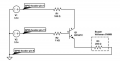
I need to use the circuit in the attached diagram where I will be driving the transistor base from a 3.3V GPIO. For the transistor collector I will be connecting a 5V supply instead af 3.3V.
What equation can I use to determine the resistors values (without assuming resistor values) ?
I need to use the circuit in the attached diagram where I will be driving the transistor base from a 3.3V GPIO. For the transistor collector I will be connecting a 5V supply instead af 3.3V.
What equation can I use to determine the resistors values (without assuming resistor values) ?
Attachments
-
 32.3 KB Views: 16
Last edited:


