Calculating current through resistor

Thread Starter

Emil Skovgaard

Joined Jun 6, 2015
37
That's because i'm from Europe, but i will the . instead of ,

Can you help me walk through this?
The voltage drop across R1 is calculated by saying (300 ohm * 6 amp = 1.800 V) Is that right?

From there i use resistors in parallel, and my R23 is 150 Ohm.

Then i use I =V/R. And as i know 1.800 is dropped, only 600 V is left, so i insert that. I = 600/150 = 4 amps.

Then there is 2 amps left for R4, and that voltage drop across the resistor is therefore (200 * 2 amp = 400 V)

Then i use the resistor in parallel again. I know that 400 volt has dropped from 1.800 leaving me with 200 volt, and i use that in the formula.

200/100 = 2 amps.

And by that i have calculated that current through the resistors? You may check through the calculation :)
 

ian field

Joined Oct 27, 2012
6,536
Hi,

Have been sitting with this question for some time now, and about to got nuts. I know how to do it when its with volt as input, but this time it is amps. I have been calculating back and forth and i gives me 6 amps (which is the number to start with).
Hoping someone can help me out :)

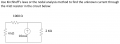
View attachment 86773
The easy way is download the table of Ohm's law equations.

There are 4 groups of equations, each group gives the answer in V, A, R or W respectively.

Pick the group that gives you the result in the unit you want, and select from that group the equation that includes the units you have.
 

ian field

Joined Oct 27, 2012
6,536
I have calculated resistors in parallel, so R23 ended up being 150ohm, and R56 being 100. From there i used knowledge about resistors in series, and now i have two resistors. R123 being 350 ohm, and R456 being 300 ohm. From there on im not quite sure what to do?
Being too lazy to keep turning fractions upside down, I just apply a hypothetical voltage to all the resistors and sum the current.

Then I just have to calculate the resistance from the hypothetical voltage and total current.
 

WBahn

Joined Mar 31, 2012
33,019
That's because i'm from Europe, but i will the . instead of ,
I know. If you can use the other convention, that's great, but we can deal with it either way. Probably the best way is to only use the radix point and not use the thousands separator at all.

Can you help me walk through this?
Sure. I won't do it for you, but I'll give hints and let you know if you go astray. You are doing a pretty good job of putting forth your own effort, so I don't foresee any problems.

The voltage drop across R1 is calculated by saying (300 ohm * 6 amp = 1.800 V) Is that right?
Correct. But let's write it as 1800 V.

From there i use resistors in parallel, and my R23 is 150 Ohm.
Correct. Note that units are not capitalized (with very rare exception) even if they are someone's last name. Also, if you working with a standard keyboard, you can get the Ω symbol by holding down the 'Alt' key and typing 234 on the numeric keypad. You can also get it by bringing up the Symbol keyboard by clicking the big S icon at on the toolbar at the top of the edit pane. But typing out the units is fine -- and thank you far starting to use them without me harping on you. It's much appreciated.

Then i use I =V/R. And as i know 1.800 is dropped, only 600 V is left, so i insert that. I = 600/150 = 4 amps.
Now I'll harp a bit. It's I = 600V/150Ω = 4 A. The units are a part of the value. 600/150 is just a number, it is not a current.

Then there is 2 amps left for R4, and that voltage drop across the resistor is therefore (200 * 2 amp = 400 V)
Correct.

Then i use the resistor in parallel again. I know that 400 volt has dropped from 1.800 leaving me with 200 volt, and i use that in the formula.
It might have been just a typo, but the 400 V is dropped from the 600 V, not the 1800 V. But, yes, you are left with 200 V across R5/R6.

200/100 = 2 amps.
Yes. And now you have a simple check because you have 2 A in each of R5 and R6 based on Ohm's Law and that must mean, by Kirchhoff's Current Law, that you have 4 A in R4, which agrees with what you determined previously. So the chances are very high that your work is correct -- which it is.
 

shteii01

Joined Feb 19, 2010
4,644
Are you familiar with concepts of Current Divider and Voltage Divider?

R2 and R3 form a current divider.
R5 and R6 form a current divider.
R23 and R456 form a current divider.
 

MrAl

Joined Jun 17, 2014
13,744
Hello again,

Since you are having a problem with this circuit let me see if i can walk you through this one, then i suggest after this you try some more circuits like this.

At first it might seem difficult, but once you learn a few tricks you start to do this quickly.

With a circuit like this it is usually pretty easy to combine resistances and then start to solve for voltages and currents. That's the first step in many circuits. Some circuits wont allow you to combine resistances easily however, and that means you should eventually learn Nodal Analysis as that is a very general way to solve circuits.

Since we can combine resistances with this circuit, lets do that first. If you already figured some of this out that's great, but i'll start from the beginning anyway.

Starting with R5 and R6, we combine them in parallel.that gives you a resistance we'll call R56. Now you may replace R5 and R6 with this new resistor, and draw it in place in a drawing program if you want to keep traick of it, or just keep a mental note.
BTW, two resistors in parallel are computed with:
Rp=Ra*Rb/(Ra+Rb

After we do that, we see that it is now in series with R4, so we add the two:
R456=R4+R56

and now we replace the entire right side of the circuit with R456, and that means we only have four resistors in the circuit.

Next, we see that with R4, R5, and R6 replaced with R456 that we now have R2, R3, and R456 in parallel. That's three resistors in parallel now, so we combine them using:
Rp=1/(1/Ra+1/Rb+1/Rc)

and doing this gives us what we'll call R23456. This resistor is a series and parallel combination of the named resistors as calculated above. So now we only have two resistors:
R1 and R23456, and they are connected in series.

Now since they are connected in series they form a voltage divider, and if they were powered by a voltage source we could use the formula for a voltage divider:
Vout=Vin*Rb/(Ra+Rb)

where Ra is the upper resistor and Rb is the lower resistor, but since they are powered by current source and we have the rule:
"Current in a series circuit is the same in every element"

all we have to do to calculate the voltage at the junction is to multiply R23456 times the current because Ohm's Law states:
V=I*R

so knowing the current and the new resistance, we multiply and we get the voltage:
V=I*R23456.

Now that we have the voltage we can solve for the currents and voltages in all the resistors R2,R3, etc. We can also use Ohm's Law to calculate the voltage across R1:
V1=I*R1

and so we know the total voltage from the left side of R1 to ground by adding the two voltages just found.

If this is your first resistor circuit or one of your first however i would recommend doing simpler circuits first, like with one resistor, then two resistors, then three, etc., until you have mastered those circuits. These multi resistor circuits become easier then.
I would also recommend thinking about learning Nodal Analysis at some point, because that is a very general method.

You might also mention what kind of math you have had in the past too, such as algebra, trig, in particular do you do any simultaneous equations?
 

Thread Starter

Emil Skovgaard

Joined Jun 6, 2015
37
Thanks for the help, i really appreciate the step-to-step guidens and help. Gave me a real good understanding, and have made it easier to solve the other assignments i'm dealing with. Thanks for taken the time :)
 

Thread Starter

Emil Skovgaard

Joined Jun 6, 2015
37
As i work through the rest of my exercises i stumble across a similar exercise as the first mentioned.

Circuit2.png

Is it the same procedure as the last? In this case, does the 10mA split at the top, so 5mA flows right, and 5mA flows left?
 

Jony130

Joined Feb 17, 2009
5,598
The current will split, but not in half. In fact the current through 4kΩ resistor will be 5/2 = 2.5 smaller than 2k resistor current.
And procedure should be the same
 

Thread Starter

Emil Skovgaard

Joined Jun 6, 2015
37
Isn't the current splitting at the top? So 5mA flows right, and 5mA left? When that is not the case who does that differ from how current splits? I know that the 5mA won't reach the 4 k resistor as some is lost over the 1k resistor, and that how i have calculated it so far..

But if the current does not split at the top, i need som elaboration on how current splits in circuits i guess?
 

Jony130

Joined Feb 17, 2009
5,598
Isn't the current splitting at the top?
Yes the current will "split" at the top node.
In this circuit we have a two closed loop paths for current to flow.
1.PNG
As you can see 10mA (Itot) at top junction will split into I1 current and I2 current.
I1 current will flow through 1kΩ and 4kΩ resistor and back to the source.

I2 current will flow from top junction (node) through 2kΩ resister back to the source.

And from the first Kirchhoff's law we can say that:
Itot = I1 + I2


So 5mA flows right, and 5mA left?
No. Why do you assume that the current will split into equal halves?

When that is not the case who does that differ from how current splits?
How the current will splits depend only on resistors values.
I2/I1 = (1kΩ +4kΩ)/2kΩ = 2.5

I know that the 5mA won't reach the 4 k resistor as some is lost over the 1k resistor, and that how i have calculated it so far..
How can current be "lost" in resistor ?
http://forum.allaboutcircuits.com/attachments/40_1211642965-jpg.40686/
http://forum.allaboutcircuits.com/attachments/17_1211642949-jpg.40685/
In this part of a circuit 1kΩ resistor in series with 4kΩ resistor we have a voltage is divider not the current.
Some total voltage will we drop across 1kΩ resistor.
 

Thread Starter

Emil Skovgaard

Joined Jun 6, 2015
37
Of course not lose of current, but voltage over the resistor, my bad.

I understand that the current split at the top, but i can't quite follow the way you calculate it? Or well, i can, but not how much current goes each way? I see the 2.5, but what is that number compared to what?

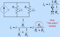
Couldn't i just use current division? I tried doing that, and used resistor in series, to make one resistor out of 1k and 4k. From there i could use the current division:

Skærmbillede 2015-06-10 kl. 14.50.15.png

And i ended up having 7mA going one way, and 3mA going the other way (can show the calculations if needed). Is that the wrong way to go? From there i can calculate the current through the 4k resistor.
 

Jony130

Joined Feb 17, 2009
5,598
But still your answer is wrong. Why ?
V2 = 7mA * 2kΩ = 14V and V1 = 3mA * 5kΩ = 15V
V1 is not equal to V2 voltage and this is why we can say that your answer is wrong. Because for resistors connected in parallel the voltage must be the same V1 = V2.
 

Thread Starter

Emil Skovgaard

Joined Jun 6, 2015
37
@Jony130

Not entirely right. I was just picky and rounded the numbers. I1 was 0,00285 = 14,25, and I2 was 0,00714 = 14,28
If i had taken all the decimals it would have matched the voltage i found for the circuit as i show in the calculate down below


Okay. I will give a shot at what i found out so far, please correct me if wrong or right!

First of all i use current division, to calculate in which way the current divide at the node. To do that, at use resistors in parallel on the left side og the circuit so i only have two resistors.

From there i make my two equations:

I1 = 0,01 A * 2000/7000 = 0,00285 A
I2 = 0,01 A * 5000/7000 = 0,00714 A

From now i see the 5k resistor as two individuals again as 1k and 4k

At first i calculate the amount of volt the circuit produce. This is done by the procedure on last page (also calculated to check if wrong or right) and gives 14,28 V

Now i can calculate the voltage drop across R1.
Vd = 1000 ohm * 0,00714 A = 7,14 V

Now i'm left with 7,14 V. From here i can calculate the current through the 4k resistor.

I = V/R

7,14 V / 4000 ohm = 0,0017 A
 

Jony130

Joined Feb 17, 2009
5,598
From there i make my two equations:

I1 = 0,01 A * 2000/7000 = 0,00285 A
I2 = 0,01 A * 5000/7000 = 0,00714 A
Next time use mA instead of a amperes. Also notice that if you have a current in milliamperes and resistor in kilo ohms the result will be in voltage (2mA * 3kΩ = 6V).

I1 = 10mA * 2kΩ/7kΩ = 2.857mA
I2 = 10mA * 5kΩ/7kΩ = 7.142mA

Now i can calculate the voltage drop across R1.
Vd = 1000 ohm * 0,00714 A = 7,14 V
Wrong, 7.141mA is not the current that is flow through 1k resistor.
And this is why the rest of your calculations are also wrong.
Also can you tell me why do you think that the 4k resistor current is different in value than 1k resistor current?
 

Thread Starter

Emil Skovgaard

Joined Jun 6, 2015
37
Am rather new to electrical circuits and such, so i'm not quite sure. But as you said, there is not current drop in a circuit, so therefore i would assume that the current through the 1k resistor is the same as through the 4k resistor?
 
Top