Burnt out resistor

dl324

Joined Mar 30, 2015
18,339
As an example it gives me me a reading of 576mV voltage drop with the -ve on the base and the +ve on the Collector. Am I missing something.
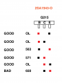
On a good transistor, you'll get something around 700mV (576mV is close enough) when the junction is forward biased (red lead on the anode, black lead on the cathode), and open circuit when it's reverse biased. Having two good junctions isn't sufficient. You need to do a test across the collector-emitter to see if it's short.

I managed to kill a 2N3442 transistor (with no heat sink) when I was doing a load test on a transformer with a 56VAC secondary. I had been testing lower power transformers earlier and forgot to be mindful of power dissipation in the transistor. It blew the fuse in my test setup and realized I was trying to make it dissipate several hundred watts (the transformer ended up being capable of 4.5A). Both junctions appear to test good, but there's a C-E short.
 

Thread Starter

Squidge75

Joined Feb 12, 2024
25
Hi there Dennis. I just did a more thorough test with the suspect Transistor. Measuring more options. Similar to yours the C-E connection should be reading OL but its reading 650. Would this be a good sign that the transistor is defunked?

Also, one other question, I am getting a lot of 056 with long beeps on the other transistors. Could someone explain what this means?
 

Attachments

dl324

Joined Mar 30, 2015
18,339
Similar to yours the C-E connection should be reading OL but its reading 650. Would this be a good sign that the transistor is defunked?
I'd say so. It should measure open circuit both directions. Remove the transistor and test again to confirm.
I am getting a lot of 056 with long beeps on the other transistors. Could someone explain what this means?
Might be something specific to your meter. I get a continuous beep for shorts on several of my meters.

I usually use a continuity tester for testing diode junctions. I don't have to look away to see the result.
junctionTestContinuityTester.jpg
It lights dimly for a good junction, brighter for a short.
 

Thread Starter

Squidge75

Joined Feb 12, 2024
25
Ah ha just noticed in the small print of the manual, the Diode and Continutity mode seem to be on the same place on the dial. A continuous buzzer means that it is a good connection.

OI will remove the transistor though and test it again. One question… the transistors are attacehd to the Heatsink with thermo material. Is there a suggested way of removing them? I dont want to damage the heatsink. Thanks
 

dl324

Joined Mar 30, 2015
18,339
the transistors are attacehd to the Heatsink with thermo material. Is there a suggested way of removing them?
Thermal paste/grease isn't an adhesive, so you can remove without damaging anything. When you reinstall, you need to remove the old grease and apply new. A thin coat is all that's required. It just fills small voids on the mating surfaces.

Be mindful of any insulators that might have been used.
 

Thread Starter

Squidge75

Joined Feb 12, 2024
25
Also out of curiosity, I just tested the 6 smaller transistors again. None of these show any OL in any configuraion of +ve and -ve. (Q216, Q213, Q214, Q114, Q113, Q116) These are NPN BJT transistors. Surely all 6 couldnt have gone?
 

Thread Starter

Squidge75

Joined Feb 12, 2024
25
Thermal paste/grease isn't an adhesive, so you can remove without damaging anything. When you reinstall, you need to remove the old grease and apply new. A thin coat is all that's required. It just fills small voids on the mating surfaces.

Be mindful of any insulators that might have been used.
Ah fantastic thanks. it just looked like there was some kind of paper, or material between the heatsink and the back of the transistor.
 

Attachments

dl324

Joined Mar 30, 2015
18,339
None of these show any OL in any configuraion of +ve and -ve. (Q216, Q213, Q214, Q114, Q113, Q116) These are NPN BJT transistors.
It depends on the voltage your tester uses for diode checks. I think all of mine use a couple volts because I can't test white/blue LEDs. If it's above 5V, it could be breaking down the base-emitter junctions; which is bad.
 

Thread Starter

Squidge75

Joined Feb 12, 2024
25
It depends on the voltage your tester uses for diode checks. I think all of mine use a couple volts because I can't test white/blue LEDs. If it's above 5V, it could be breaking down the base-emitter junctions; which is bad.
ok thanks ill look into that. Thanks so much for all the advice. Great that one can come onto forums like this and get all the help they need. Ill let you know how the removal goes.
 

dl324

Joined Mar 30, 2015
18,339
it just looked like there was some kind of paper, or material between the heatsink and the back of the transistor.
That looks like an old-school silicon pad to me:
LM317Manhattan.jpg

You don't need any thermal paste in that case because you can reuse the pad.
 

Thread Starter

Squidge75

Joined Feb 12, 2024
25
i guess if 10 years counts as old scholl then could well be. SOme of the transistors arnt in production any longer.
 

Thread Starter

Squidge75

Joined Feb 12, 2024
25
Ok then , so I just tested the removed the suspect transistor. And the e-c reading that was showing 650 in circuit, is now showing OL. Which suggests this is ok?
 

dl324

Joined Mar 30, 2015
18,339
Ok then , so I just tested the removed the suspect transistor. And the e-c reading that was showing 650 in circuit, is now showing OL. Which suggests this is ok?
If it shows open circuit both directions, and both junctions test good, I'd say it's good.

Other components in the circuit could be affecting readings. Which transistor was it? How were the leads connected when it read as a diode?
 

Thread Starter

Squidge75

Joined Feb 12, 2024
25
the transistor was Q215. I connected the leads in both directions. I connected the leads to the Transistor in all variations. But maybe I am misunderstanding?
 

dl324

Joined Mar 30, 2015
18,339
the transistor was Q215. I connected the leads in both directions. I connected the leads to the Transistor in all variations. But maybe I am misunderstanding?
If Q214 is shorted, that would affect readings on Q215. Q214 is the transistor that would have damaged R281.
1708026368883.png
 

Thread Starter

Squidge75

Joined Feb 12, 2024
25
Hi there again. I made some good progress on my Amp. And then made some back progress. I installed new resistors and transistors and the amp was working perfectly.

I then went to check the idle current and whilst doing so I mnaged to blow what I think is called a Jumper Wire? I have attaced an image of it. But anyway now my amp obviolsy wont turn on. I am presuming I may have damaged other things as well but I will change the wire first.

Is anyone able to point me in the direction of what I should be buying. To be honest I am a little unsure of what to even look for as there are no part numbers. I have found types of wire that are quite cheap but then other insulated jumper wires that are very expensive. Also how do I know what thickness to buy,

Thanks so much for any help
 

Attachments

Top