I am attempting to design a simple LDO using discrete components to better understand, analyze the workings of the feedback loop. I have no prior experience in doing this so am currently picking 'random' parts to use as the pass transistor, error amplifier. I'm thinking about using a 1.2 V bandgap voltage reference circuit for the reference, but currently just have a 1.2 V voltage source connected to it.
For this project, I don't have any specific requirements (other than for it to work and not oscillate ). For now I have 5 V at the input, and matched resistive divider to give me 2.4 V at the output. I simulated it, and it looks ok w/ no load or only a resistive load attached to it.
I am running into issues (oscillations) when I attempt to do a load step. I've tried varying the rise / fall times of the load, magnitude, etc, but it seems no matter what, the system oscillates.
Any suggestions on what may be causing this? Also, what discrete op-amp is a good recommendation for use as an error amp? Pass transistor? I only need to step from 0 to 1 A (at most). Again, no real specific requirements. Just want the thing to work!
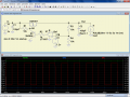
For this project, I don't have any specific requirements (other than for it to work and not oscillate
). For now I have 5 V at the input, and matched resistive divider to give me 2.4 V at the output. I simulated it, and it looks ok w/ no load or only a resistive load attached to it.I am running into issues (oscillations) when I attempt to do a load step. I've tried varying the rise / fall times of the load, magnitude, etc, but it seems no matter what, the system oscillates.
Any suggestions on what may be causing this? Also, what discrete op-amp is a good recommendation for use as an error amp? Pass transistor? I only need to step from 0 to 1 A (at most). Again, no real specific requirements. Just want the thing to work!
Attachments
-
 51.3 KB Views: 175
 -
 79.6 KB Views: 88
 -
 30.8 KB Views: 76