Facebook
 Google
 GitHub
 Linkedin
Hello,
I am designing a buck converter ... very basic... open loop. I am giving 12V as input and expecting the output to be changing from 0 - 12v with a duty cycle range of 10 - 90%. I have taken a circuit reference from a website.
https://electronoobs.io/uploads/tutorial_files/210/image_1_727_.png (the P-mosfet pin representation is wrong in the picture... I have corrected in my circuit).
My circuit:


I did some trials ... here are the results.
Case 1: Fs = 1KHz; The output voltage is changing from 0 - 12v with a duty cycle range of 5% to 15%
 o/p = 63mV; Duty Cycle = 5%
 o/p = 12 V; Duty Cycle = 15%
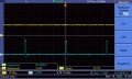
Case 2: Fs = 30KHz; The output voltage is changing from 0 - 12v with a duty cycle range of 40% to 50%
 o/p = 187mV; Duty Cycle = 40%
 o/p = 12.5V; Duty Cycle = 50%
My question is, how can I control the voltage from 0 - 12v with a duty cycle range of 10 - 90 %. Actually the circuit which I took as reference is based on ARduino controller (pulse height is 5V).... But I am working with NodeMcu(ESP8266) whose pulse height is 3.3V. Did I do any mistake with NPN gate resistor? Based on a rough calculation I got the base resistor is around 1.5 MegaOhm.
I am designing a buck converter ... very basic... open loop. I am giving 12V as input and expecting the output to be changing from 0 - 12v with a duty cycle range of 10 - 90%. I have taken a circuit reference from a website.
https://electronoobs.io/uploads/tutorial_files/210/image_1_727_.png (the P-mosfet pin representation is wrong in the picture... I have corrected in my circuit).
My circuit:
I did some trials ... here are the results.
Case 1: Fs = 1KHz; The output voltage is changing from 0 - 12v with a duty cycle range of 5% to 15%
o/p = 63mV; Duty Cycle = 5%o/p = 12 V; Duty Cycle = 15%Case 2: Fs = 30KHz; The output voltage is changing from 0 - 12v with a duty cycle range of 40% to 50%
o/p = 187mV; Duty Cycle = 40%o/p = 12.5V; Duty Cycle = 50%My question is, how can I control the voltage from 0 - 12v with a duty cycle range of 10 - 90 %. Actually the circuit which I took as reference is based on ARduino controller (pulse height is 5V).... But I am working with NodeMcu(ESP8266) whose pulse height is 3.3V. Did I do any mistake with NPN gate resistor? Based on a rough calculation I got the base resistor is around 1.5 MegaOhm.