Facebook
 Google
 GitHub
 Linkedin
Hello,
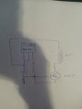
I am very new to electronics and am really just learning about transistors and some basic sensors. I am looking to create a simple circuit using a hall effect sensor and a transistor to turn on and off a single coil to make a very simple BLDC. I have been successful in wiring the Hall effect ( 1751 948E) and also getting my transistor (TIP115) to work...separately. The problem is when i try to use the output from the hall effect to switch the transistor. The output from the hall effect is 3 mV and is not sufficient to saturate the transistor. I need help in creating a circuit to amplify the 3mV to switch the transistor or any suggetions on how to do this. Any help would be great. Thank you for your time")
A
I am very new to electronics and am really just learning about transistors and some basic sensors. I am looking to create a simple circuit using a hall effect sensor and a transistor to turn on and off a single coil to make a very simple BLDC. I have been successful in wiring the Hall effect ( 1751 948E) and also getting my transistor (TIP115) to work...separately. The problem is when i try to use the output from the hall effect to switch the transistor. The output from the hall effect is 3 mV and is not sufficient to saturate the transistor. I need help in creating a circuit to amplify the 3mV to switch the transistor or any suggetions on how to do this. Any help would be great. Thank you for your time
A