Facebook
 Google
 GitHub
 Linkedin
Hello,
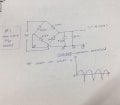
I was testing a bridge rectifier using 4 germanium diodes (1N60). The output should look like a sine squared plot with only positive voltage but I am getting the same shape but with average voltage zero (basically the final waveform has a negative DC bias). This is highly undesirable for my project.
PS: I tried Schottky diodes with same issue and I cannot use silicon diodes or bridge rectifier ICs. This is application specific so I cannot use batteries or clampers either.
Can someone please suggest a solution?
Thanks!