BPSK Waveform

Thread Starter

tapajitm

Joined Mar 3, 2017
7
Hello,

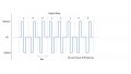
The following is a Data waveform modulated as shown in the image. Can someone guide me how to generate the waveform using a MCU / FPGA. I am trying to figure out how to jump between the voltage rails quick enough to generate an acceptable waveform.
 

Attachments

crutschow

Joined Mar 14, 2008
34,285
Does the signal have to go between plus and minus, or can it be between zero and a positive voltage, as is common for digital signals?
 

Thread Starter

tapajitm

Joined Mar 3, 2017
7
That BPSK uses a Sine wave as a carrier. The waveform I got is what I need to communicate with a two decade old naval computer system.

If all the voltage rails were positive, I could've used a 2 bit R2R DAC and use a Look Up Table on the mcu. But I can't figure out how to generate the negative voltage rails.
 

AlbertHall

Joined Jun 4, 2014
12,345
To get a negative voltage you're going to need a negative supply and, given that, you can do it with two mcu pins and some resistors.
 

AlbertHall

Joined Jun 4, 2014
12,345
The circuit below assumes the two logic inputs are 0V to 5V and that a -5V supply is available. V3 and V4 represent the two logic inputs and you can see it produces a three level output matching the required voltage levels. When both V3 and V4 are 0V the output is -300mV. When either of the inputs is at 5V and the other is at 0V the output is 0V. When both inputs are 5V the output is +300mV. I have not attempted to replicate waveform you require and you would need to get the MCU to produce the correct inputs to this circuit.
upload_2017-9-4_12-23-12.png
upload_2017-9-4_12-21-38.png
 

Attachments

simozz

Joined Jul 23, 2017
125
Hello,
If you have a fast enough op-amp you could test a Schmitt Trigger:

trigger.png

Where Vctl is the output from the MCU or FPGA, and Vref is a reference voltage to trigger the negative output.
You should choose threshold values on positive feedback.
If you don't use a rail-to-rail output, V+ and V- should be something more than 5 V, depending on the voltage drop.
simozz
 

AlbertHall

Joined Jun 4, 2014
12,345
The op-amp circuit doesn't limit the output to ±305mV as requested by TS. You might be able to add that with a simple potential divider but the op-amp output is unlikely to be symmetrical enough for that.
 

Thread Starter

tapajitm

Joined Mar 3, 2017
7
The circuit below assumes the two logic inputs are 0V to 5V and that a -5V supply is available. V3 and V4 represent the two logic inputs and you can see it produces a three level output matching the required voltage levels. When both V3 and V4 are 0V the output is -300mV. When either of the inputs is at 5V and the other is at 0V the output is 0V. When both inputs are 5V the output is +300mV. I have not attempted to replicate waveform you require and you would need to get the MCU to produce the correct inputs to this circuit.
View attachment 134278
View attachment 134276
Thank you Mr.Hall. Ideally I would like to have a ZERO output when the inputs are open or at logic low. Could you please advice how can I do it differently ?

Moreover I would be putting Opto-isolators at the digital input, and unit gain buffer at the analog side. Any suggestion on the selection on the op-amp ??
 
Top