BLDC Controller using STM32 and DRV8301

Thread Starter

KranthiKumarR

Joined Aug 27, 2017
18
Hello everyone,

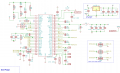
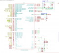
I have built a hardware similar to VESC by Benjamin Vedder. I have also attached the screenshots of the schematic built. I'm using STm32Cube ide to code.
Below is a simple code I have written to check for the output on one phase. I'm able to see the PWM on an Oscilloscope from the MCU. But I'm unable to see any output on the drv8301 outputs. Is there any configuration to be set on drv8301 to generate the outputs. please suggest

I'm using a Power supply and have gone upto 20V on V_supply

PWM on highside mosfet H1-PA8
On on lowside mosftet L2-PB14
EN_GATE-PB5

HAL_TIM_PWM_Start(&htim1, TIM_CHANNEL_1);


while (1)
{

HAL_GPIO_WritePin(GPIOB, GPIO_PIN_5, GPIO_PIN_SET);

TIM1->CCR1 = 50000;
HAL_GPIO_WritePin(GPIOA, GPIO_PIN_14, GPIO_PIN_SET);


}
 

Attachments

FlyingDutch

Joined Mar 16, 2021
83
Hello,

first you have to write code initializing all cloks in MCU, then initialize GPIO and other components. After that you should be able to use GPIO and other components. In main function it can look similiar to this (this is main from one of my applications):

Main function:
int main(void)
{
  /* USER CODE BEGIN 1 */

  /* USER CODE END 1 */

  /* MCU Configuration--------------------------------------------------------*/

  /* Reset of all peripherals, Initializes the Flash interface and the Systick. */
  HAL_Init();

  /* USER CODE BEGIN Init */

  /* USER CODE END Init */

  /* Configure the system clock */
  SystemClock_Config();

  /* USER CODE BEGIN SysInit */

  /* USER CODE END SysInit */

  /* Initialize all configured peripherals */
  MX_GPIO_Init();
  MX_TIM1_Init();
  MX_TIM2_Init();
  MX_TIM3_Init();
  MX_USART2_UART_Init();

  /* USER CODE BEGIN 2 */

  TLC5920_startup();
  TLC5920_clear();            // Clears display

   uint8_t cx, cy;            // Loop counters.

     for (cy = 0; cy < 8; cy++)
     {
       for (cx = 0; cx <16; cx++)
       {

           //if (cy%2==0)
           /*if (cx%2==0)*/ matrix[cy] [cx] = 255;       // Blank each pixel in turn.
           //else matrix[cy] [cx] =0;

           matrix[cy] [cx] = 255;
       }
     }

  //Start timers
  HAL_TIM_Base_Start(&htim1);
  HAL_TIM_Base_Start_IT(&htim2);
  HAL_TIM_Base_Start_IT(&htim3);

  /* USER CODE END 2 */

  /* Infinite loop */
  /* USER CODE BEGIN WHILE */
  while (1)
  {
    /* USER CODE END WHILE */
        //TLC5920_refresh();

         for (cy = 0; cy < 8; cy++)
         {
           for (cx = 0; cx <16; cx++)
           {

               if (cy%2==0)
               if (cx%2==0) matrix[cy] [cx] = 255;       // Blank each pixel in turn.
               else matrix[cy] [cx] =0;

               //matrix[cy] [cx] = 255;
           }
         }

    /* USER CODE BEGIN 3 */
  }
  /* USER CODE END 3 */
}
Clocks initialization code SystemClock_Config() function for my applicstion looks like:
SystemClock_Config() function:
/**
  * @brief System Clock Configuration
  * @retval None
  */
void SystemClock_Config(void)
{
  RCC_OscInitTypeDef RCC_OscInitStruct = {0};
  RCC_ClkInitTypeDef RCC_ClkInitStruct = {0};

  /** Initializes the RCC Oscillators according to the specified parameters
  * in the RCC_OscInitTypeDef structure.
  */
  RCC_OscInitStruct.OscillatorType = RCC_OSCILLATORTYPE_HSI;
  RCC_OscInitStruct.HSIState = RCC_HSI_ON;
  RCC_OscInitStruct.HSICalibrationValue = RCC_HSICALIBRATION_DEFAULT;
  RCC_OscInitStruct.PLL.PLLState = RCC_PLL_ON;
  RCC_OscInitStruct.PLL.PLLSource = RCC_PLLSOURCE_HSI_DIV2;
  RCC_OscInitStruct.PLL.PLLMUL = RCC_PLL_MUL16;
  if (HAL_RCC_OscConfig(&RCC_OscInitStruct) != HAL_OK)
  {
    Error_Handler();
  }
  /** Initializes the CPU, AHB and APB buses clocks
  */
  RCC_ClkInitStruct.ClockType = RCC_CLOCKTYPE_HCLK|RCC_CLOCKTYPE_SYSCLK
                              |RCC_CLOCKTYPE_PCLK1|RCC_CLOCKTYPE_PCLK2;
  RCC_ClkInitStruct.SYSCLKSource = RCC_SYSCLKSOURCE_PLLCLK;
  RCC_ClkInitStruct.AHBCLKDivider = RCC_SYSCLK_DIV1;
  RCC_ClkInitStruct.APB1CLKDivider = RCC_HCLK_DIV2;
  RCC_ClkInitStruct.APB2CLKDivider = RCC_HCLK_DIV1;

  if (HAL_RCC_ClockConfig(&RCC_ClkInitStruct, FLASH_LATENCY_2) != HAL_OK)
  {
    Error_Handler();
  }
}
GPIO initializations looks like this:

MX_GPIO_Init() function:
/**
  * @brief GPIO Initialization Function
  * [USER=120004]@Param[/USER] None
  * @retval None
  */
static void MX_GPIO_Init(void)
{
  GPIO_InitTypeDef GPIO_InitStruct = {0};

  /* GPIO Ports Clock Enable */
  __HAL_RCC_GPIOC_CLK_ENABLE();
  __HAL_RCC_GPIOD_CLK_ENABLE();
  __HAL_RCC_GPIOA_CLK_ENABLE();
  __HAL_RCC_GPIOB_CLK_ENABLE();

  /*Configure GPIO pin Output Level */
  HAL_GPIO_WritePin(LD2_GPIO_Port, LD2_Pin, GPIO_PIN_RESET);

  /*Configure GPIO pin Output Level */
  HAL_GPIO_WritePin(GPIOB, CSEL0_Pin|CSEL1_Pin|CSEL2_Pin|DSEL_Pin
                          |BLANK_Pin|LATCH_Pin|SCLK_Pin|SIN_Pin
                          |REZ01_Pin, GPIO_PIN_RESET);

  /*Configure GPIO pin : B1_Pin */
  GPIO_InitStruct.Pin = B1_Pin;
  GPIO_InitStruct.Mode = GPIO_MODE_IT_FALLING;
  GPIO_InitStruct.Pull = GPIO_NOPULL;
  HAL_GPIO_Init(B1_GPIO_Port, &GPIO_InitStruct);

  /*Configure GPIO pins : PC0 PC1 PC2 PC3
                           PC4 PC5 PC6 PC7
                           PC8 PC9 PC10 PC11
                           PC12 */
  GPIO_InitStruct.Pin = GPIO_PIN_0|GPIO_PIN_1|GPIO_PIN_2|GPIO_PIN_3
                          |GPIO_PIN_4|GPIO_PIN_5|GPIO_PIN_6|GPIO_PIN_7
                          |GPIO_PIN_8|GPIO_PIN_9|GPIO_PIN_10|GPIO_PIN_11
                          |GPIO_PIN_12;
  GPIO_InitStruct.Mode = GPIO_MODE_ANALOG;
  HAL_GPIO_Init(GPIOC, &GPIO_InitStruct);

  /*Configure GPIO pins : PA0 PA1 PA4 PA6
                           PA7 PA8 PA9 PA10
                           PA11 PA12 PA15 */
  GPIO_InitStruct.Pin = GPIO_PIN_0|GPIO_PIN_1|GPIO_PIN_4|GPIO_PIN_6
                          |GPIO_PIN_7|GPIO_PIN_8|GPIO_PIN_9|GPIO_PIN_10
                          |GPIO_PIN_11|GPIO_PIN_12|GPIO_PIN_15;
  GPIO_InitStruct.Mode = GPIO_MODE_ANALOG;
  HAL_GPIO_Init(GPIOA, &GPIO_InitStruct);

  /*Configure GPIO pin : LD2_Pin */
  GPIO_InitStruct.Pin = LD2_Pin;
  GPIO_InitStruct.Mode = GPIO_MODE_OUTPUT_PP;
  GPIO_InitStruct.Pull = GPIO_NOPULL;
  GPIO_InitStruct.Speed = GPIO_SPEED_FREQ_LOW;
  HAL_GPIO_Init(LD2_GPIO_Port, &GPIO_InitStruct);

  /*Configure GPIO pins : CSEL0_Pin CSEL1_Pin CSEL2_Pin LATCH_Pin */
  GPIO_InitStruct.Pin = CSEL0_Pin|CSEL1_Pin|CSEL2_Pin|LATCH_Pin;
  GPIO_InitStruct.Mode = GPIO_MODE_OUTPUT_PP;
  GPIO_InitStruct.Pull = GPIO_NOPULL;
  GPIO_InitStruct.Speed = GPIO_SPEED_FREQ_HIGH;
  HAL_GPIO_Init(GPIOB, &GPIO_InitStruct);

  /*Configure GPIO pins : PB10 PB11 PB12 PB13
                           PB14 PB15 */
  GPIO_InitStruct.Pin = GPIO_PIN_10|GPIO_PIN_11|GPIO_PIN_12|GPIO_PIN_13
                          |GPIO_PIN_14|GPIO_PIN_15;
  GPIO_InitStruct.Mode = GPIO_MODE_ANALOG;
  HAL_GPIO_Init(GPIOB, &GPIO_InitStruct);

  /*Configure GPIO pin : PD2 */
  GPIO_InitStruct.Pin = GPIO_PIN_2;
  GPIO_InitStruct.Mode = GPIO_MODE_ANALOG;
  HAL_GPIO_Init(GPIOD, &GPIO_InitStruct);

  /*Configure GPIO pin : DSEL_Pin */
  GPIO_InitStruct.Pin = DSEL_Pin;
  GPIO_InitStruct.Mode = GPIO_MODE_OUTPUT_PP;
  GPIO_InitStruct.Pull = GPIO_PULLUP;
  GPIO_InitStruct.Speed = GPIO_SPEED_FREQ_HIGH;
  HAL_GPIO_Init(DSEL_GPIO_Port, &GPIO_InitStruct);

  /*Configure GPIO pins : BLANK_Pin SCLK_Pin */
  GPIO_InitStruct.Pin = BLANK_Pin|SCLK_Pin;
  GPIO_InitStruct.Mode = GPIO_MODE_OUTPUT_PP;
  GPIO_InitStruct.Pull = GPIO_PULLDOWN;
  GPIO_InitStruct.Speed = GPIO_SPEED_FREQ_HIGH;
  HAL_GPIO_Init(GPIOB, &GPIO_InitStruct);

  /*Configure GPIO pin : SIN_Pin */
  GPIO_InitStruct.Pin = SIN_Pin;
  GPIO_InitStruct.Mode = GPIO_MODE_OUTPUT_PP;
  GPIO_InitStruct.Pull = GPIO_NOPULL;
  GPIO_InitStruct.Speed = GPIO_SPEED_FREQ_LOW;
  HAL_GPIO_Init(SIN_GPIO_Port, &GPIO_InitStruct);

  /*Configure GPIO pin : REZ01_Pin */
  GPIO_InitStruct.Pin = REZ01_Pin;
  GPIO_InitStruct.Mode = GPIO_MODE_OUTPUT_PP;
  GPIO_InitStruct.Pull = GPIO_NOPULL;
  GPIO_InitStruct.Speed = GPIO_SPEED_FREQ_MEDIUM;
  HAL_GPIO_Init(REZ01_GPIO_Port, &GPIO_InitStruct);

  /* EXTI interrupt init*/
  HAL_NVIC_SetPriority(EXTI15_10_IRQn, 0, 0);
  HAL_NVIC_EnableIRQ(EXTI15_10_IRQn);

}
There are also important parts of code in files: stm32f1xx_hal_msp.c and stm32f1xx_it.c. You can automatically generate all initialization code using CuBeMX perspective of IDE. In CubeMX perspective you cab use graphical wizards for configurin g clocks and other peripherals, when everything was sett you will be able to generate application framework with code initializing all peripherals in MCU.

Best Regards
 
Last edited:

trebla

Joined Jun 29, 2019
543
I think, the DRV8301 requires 3x PWM inputs, like this:
pwm_ti.png

With one PWM input you must use DRV8305 or DRV8320 driver. Also, there is no need to put enable input control to while loop,
 
Top