Facebook
 Google
 GitHub
 Linkedin
Please can someone make my day please...Thank you for trying
Where the hell is my mistake!!!!!!!!!!!!!!!!!!!!!!!!!!!!!!
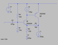
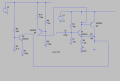
The current source is the problem...If to use spice current source it works but now not to use then base of Q1 about 7.5V but it's emitter is about 11.9V same with breadboard measurement
Please!!!!!!!!!!!
V2 is 12V..changed it but no difference..Current source is problem but can not see problem
Where the hell is my mistake!!!!!!!!!!!!!!!!!!!!!!!!!!!!!!
The current source is the problem...If to use spice current source it works but now not to use then base of Q1 about 7.5V but it's emitter is about 11.9V same with breadboard measurement
Please!!!!!!!!!!!
V2 is 12V..changed it but no difference..Current source is problem but can not see problem
Attachments
-
 357.4 KB Views: 36
 -
2.4 KB Views: 4