BJT amplifier circuit problem

Thread Starter

PsySc0rpi0n

Joined Mar 4, 2014
1,755
Hi...

I tried to solve this problem today but I had some questions about it.
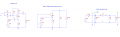
Please check the circuit attached

I was calculating Av as follows:

Av = Vout/Vin

Av = ((Re//R_load)hfe*Ib)/((Re//hie)*(Ie+Ib))

Probably my Vin is wrong but that was how I would do it! Can you explain why is this wrong?

Isn't Iin splitting into Re branch and hie branch??? Wouldn't this be my input current?
 

Attachments

Jony130

Joined Feb 17, 2009
5,487
Your equation is completely wrong. Yout BJT work as a common base amplifier. So input is at emitter. And the emitter is a input current. And this means that hie is not BJT input resistance. Ie = Ib + Ic = Ib*hfe*Ic = Ib*(hfe + 1). So hie current is equal to Ie/(hfe + 1).

Next time try to find Ve/Vs first and next Vout/Ve.
Notice that we can find Ve by inspection
Ve = Vin * (Re||Rin)/(Rs + (Re||Rin)) where Rin is a common base input resistance hib = Ve/Ie = (hie*Ib)/((hfe+1)*Ib) = hie/(hfe + 1)
 
Last edited:

Thread Starter

PsySc0rpi0n

Joined Mar 4, 2014
1,755
Your equation is completely wrong. Yout BJT work as a common base amplifier. So input is at emitter. And the emitter is a input current. And this means that hie is not BJT input resistance. Ie = Ib + Ic = Ib*hfe*Ic = Ib*(hfe + 1). So hie current is equal to Ie/(hfe + 1).

Next time try to find Ve/Vs first and next Vout/Ve.
Notice that we can find Ve by inspection
Ve = Vin * (Re||Rin)/(Rs + (Re||Rin)) where Rin is a common base input resistance hib = Ve/Ie = (hie*Ib)/((hfe+1)*Ib) = hie/(hfe + 1)
Morning Jony130.

Do we have hie in this common base amplifier? Or should we call it hib? Or we have both?

And is the hybrid model correctly assembled in LTSpice??? The one on the right in the 1st post screens?
 

Jony130

Joined Feb 17, 2009
5,487
Do we have hie in this common base amplifier? Or should we call it hib? Or we have both?
It only depends on the model (small signal) that you decided to use in this case.

And is the hybrid model correctly assembled in LTSpice??? The one on the right in the 1st post screens?
If you use model with hie than you cannot combine hie together with Re because Ib = Vbe/hie.
 

Thread Starter

PsySc0rpi0n

Joined Mar 4, 2014
1,755
It only depends on the model (small signal) that you decided to use in this case.
Well, in classes, I just know that we don't use Hybrid-Pi neither Hybrid-T. But I don't know the name of the model we use.

But what I haven't yet understood is if for any of the three types, common base/emitter/collector, we always have hie, or if for each of them we have hib, hie and hic... And if this is the case, from where to where do we have these impedances.

For instance, hie is an impedance from base to emitter. What about hib and hic?

I think I need to understand this, so that I can understand your post #2. Because if I follow the hybrid model that I have in the first post, I would say that current flowing through Re is ie, (ib*(hfe + 1)), and current flowing through hie is ib. But at your post #2, you talk about hie and later in hib. I got confused if we have hie and hib for the common base amplifier!
 
Last edited:

Jony130

Joined Feb 17, 2009
5,487
The model that you have been using in the classroom is a simplified version of a h-parameter model.
http://www.talkingelectronics.com/Download eBooks/Principles of electronics/CH-24.pdf
As for hie. hie is a input resistance for a CE amplifier
1.PNG
hie = Vbe/Ib

hib is input resistance for a CB amplifier (the resistance seen from emitter into BJT)
2.PNG

hib = Ve/Ie

Additional we know that Ve = -Vbe = -Ib*hie and Ie = - (hfe+1)*Ib so from there we can solve for hib in terms of hie:

hib = Ve/Ie = (Ib*hie)/((hfe+1)*Ib) = hie/(hfe + 1).

So hib = hie/(hfe + 1)
 

Thread Starter

PsySc0rpi0n

Joined Mar 4, 2014
1,755
Re is connected between witch two nodes?
hib is 'connected" between witch two nodes?
Re is connected from Emitter node (from the BJT) to GND and hib is from Emitter to the Base, I guess.

Edited;

But if the base is grounded, then hib would be in parallel with Re... I'm not quite sure!
 

Jony130

Joined Feb 17, 2009
5,487
Yes, exactly also notice that the base is also at GND. So this two resistors are connected to the same nodes. So how can they be connected in series ?
 

Thread Starter

PsySc0rpi0n

Joined Mar 4, 2014
1,755
Yes, exactly also notice that the base is also at GND. So this two resistors are connected to the same nodes. So how can they be connected in series ?
Ok... So hib is in parallel with Re...

If I want to use hie instead, this hie would also be in parallel with Re, right? The difference would be the current flowing them. Is this accurate?
 
Last edited:

Jony130

Joined Feb 17, 2009
5,487
So hib is in parallel with Re...
Yes
If I want to use hie instead, this hie would also be in parallel with Re, right? The difference would be the current flowing them. Is this accurate?
It will be better if you will stick with hie. As for is hie is in parallel with Re, the answer is yes but here we have exactly the same situation as we have with the Ro for CC amplifer.
 

Thread Starter

PsySc0rpi0n

Joined Mar 4, 2014
1,755
Notice that we can find Ve by inspection
Ve = Vin * (Re||Rin)/(Rs + (Re||Rin)) where Rin is a common base input resistance hib = Ve/Ie = (hie*Ib)/((hfe+1)*Ib) = hie/(hfe + 1)
I don't know if I understood this.

Isn't Ve the voltage drop across Re? Shouldn't this be
Ve = Ie*Re = Ib(hfe +1)*Re

or yet

Ve = hfe*Ib*(Re//hie)
???
 

Jony130

Joined Feb 17, 2009
5,487
I don't know if I understood this.
Ve = Vin * (Re||Rin)/(Rs + (Re||Rin))
Isn't Ve the voltage drop across Re? Shouldn't this be
Ve = Ie*Re = Ib(hfe +1)*Re
Do not forget that now we are doing a small-signal analysis and in this case (common base amplifier) Ie current (in small-signal sens) doesn't flow through Re. But notice that we have a voltage divider.

re3.PNG

Vout = Vin * R2/(R1+R2) and in this case

Ve = Vin*(Re||hib)/(Rs + (Re||hib))


But if you assume Rs = 0Ω then Ve = Vin and Ib = Vin/hie.
And current through Re resistor is Vin/Re and the transistor emitter current is (hfe+1)*Vin/hie
 

Thread Starter

PsySc0rpi0n

Joined Mar 4, 2014
1,755
Do not forget that now we are doing a small-signal analysis and in this case (common base amplifier) Ie current (in small-signal sens) doesn't flow through Re. But notice that we have a voltage divider.
But why doesn't Ie flows through Re for small signal AC analysis at a common base amplifier?


What would be R1 and R2 in your diagram?

Vout = Vin * R2/(R1+R2) and in this case
And why wouldn't Vo = -hfe*Ib*(Rc//RL)???
 

Jony130

Joined Feb 17, 2009
5,487
But why doesn't Ie flows through Re for small signal AC analysis at a common base amplifier?
11.PNG

As you can see input current splits into I1 and I2 and because Re >> hie the greater part of a Iin current will flow into BJT ( I2 >> I1).

What would be R1 and R2 in your diagram?
This equation Vout = Vin * R2/(R1 + R2) is a general equation for a voltage divider.
https://en.wikipedia.org/wiki/Voltage_divider#Resistive_divider
As we can see on my small-signal diagram R2 = Re||hib and R1 = Rs.
I'm sorry if I'm confused you. I didn't know that you don't know voltage divider equation.
 

Thread Starter

PsySc0rpi0n

Joined Mar 4, 2014
1,755
I'm sorry if I'm confused you. I didn't know that you don't know voltage divider equation.
Oh... I know about voltage divider equation. But I didn't realised that you were referring to a general equation. I thought you were trying to write an equation for the circuit we are analysing!
 

Jony130

Joined Feb 17, 2009
5,487
As I said because you always does not include Rs in your voltage gain formula. So you can simply assume Rs = 0Ω and then find voltage gain expression by using your favorite method of a circuit analysis.
 

Thread Starter

PsySc0rpi0n

Joined Mar 4, 2014
1,755
Hi...
I had exam last Friday and what are the odds that this was the amplifier that was on the exam. Unfortunately we had no time here to finish to analyse it so I could not do it because...

Probably I will have to repeat this exam. What I did at this exam probably won't be enough to finish this class.
 

ericgibbs

Joined Jan 29, 2010
18,766
Morning Psy,
Sorry to hear that you are not confident about the exam result.
Post the question you had a problem with and lets work thru it..

Analysing your recent threads and posts you seem to lack the basic knowledge regarding the working and operation of semiconductors, ie: diodes, zeners and transistors.
It is not enough IMO, to solve the mathematical equations for a particular circuit, you should try to understand how the operation of the circuit is controlled by the semiconductors and what is the circuits purpose.

Did you look thru all the further study tutorials I posted with my PM's.?

You are familiar with LTSpice, so use it as a teaching aid to check out your calculations, the plots you create should give you a better insight into the way a circuit operates.
Try to predict what will happen in a circuit operation if you change a component in the simulation circuit, use LTS to check it out.

E
 
Top