Bipolar power supply trouble

Thread Starter

Harpaggio

Joined May 20, 2025
3
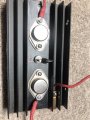
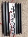
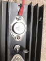
Ok, I dont normally ask for help but something is wrong with a bipolar power supply I am building and I cant figure out what. I am making 2 seperate positive outputs and two negative. I am using Lm 338 for the positive side and 333’s for the negative. Transformer is 25-0-25, to diode bridge. Positive rail voltage is 23 VDC and earth is at 0 and negative rail is -23. I have attached some pics. I have 220 ohm resistors output to Adjustment, 2800 ohm adjustment to ground. Should give me around 17.5 VDC. I get 23 VDC from right regulator output and 11 VDC from left regulator. I have triple checked everything, nothing grounded, no poor connection. Havent added anything else yet, diodes or caps.
The schematic is attached. No load on it. Whats wrong?IMG_4091.jpeg
 

Attachments

Last edited by a moderator:

sarahMCML

Joined May 11, 2019
697
In the photo showing the connections to the pins of the TO3 devices, you have the OUT pin of one connected to the IN of the other, completely wrong!
R1(?) seems correct for the upper (LM338?) regulator, but goes to the case (Input) of the of the lower regulator (LM333?) , instead of its output!
The pinouts aren't the same!
 

Thread Starter

Harpaggio

Joined May 20, 2025
3
Thank you. Both of these are 338’s. This is the positive side of the supply. Output is the case. Inputs are I and both come off a single cable from the positive connection of the bridge rectifier. Middle one is ground
I was very careful to make sure screws passed through for connections and do not earth and are isolated. Thanks for the simpler schematic. Still stuck
 

sarahMCML

Joined May 11, 2019
697
Thank you. Both of these are 338’s. This is the positive side of the supply. Output is the case. Inputs are I and both come off a single cable from the positive connection of the bridge rectifier. Middle one is ground
I was very careful to make sure screws passed through for connections and do not earth and are isolated. Thanks for the simpler schematic. Still stuck
Ah, I thought it was a plus and minus version on the same heatsink, my mistake. The only other thing I can think of is adding a 0.1uF ceramic between input and ground directly between the cases and the ground point, as suggested in the datasheet, and possibly on the outputs as well, for stability purposes.
 

MisterBill2

Joined Jan 23, 2018
27,524
CERTAINLY the 0.1mfd capacitor MUST be connected as described in the applications literature. Oscillations can produce very strange results!! One possibility could be a shorted or leaky shunt diode across the regulator. Or a damaged resistor in the voltage programming portion.
 

KeithWalker

Joined Jul 10, 2017
3,607
Do a bit of trouble shooting. Disconnect the supply input from the right regulator. Measure the output voltages. Then re connect it and disconnect the left one, measuring the voltages again. Let us know what results you get. That should help to localize the problem.
 
Top