Binary to bcd converting problem

Thread Starter

KhaledZH

Joined Oct 26, 2018
9
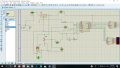
Hi. I have a project in Measurement class "Temperature sensor". The lecturer told us not to use microcontroller & Arduino so i did it with ADC0804, 74LS47 & 7 segment display.

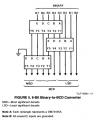
my problem is the output of the ADC0804 is binary and i tried to use DM74185a to convert it to bcd i used the circuit in datasheet but it didn't work in proteus and in my circuit and i don't know why.

if anyone know how to use it please help!
 

dl324

Joined Mar 30, 2015
16,943
Welcome to AAC!

You're going to have to give us more information before we can help you. Does the fact that 74185 is unavailable affect your decision to use it?

Is this homework? Binary to BCD conversion is a common homework question that few have solved because the ones who know how to do it don't come here for help...
 

Thread Starter

KhaledZH

Joined Oct 26, 2018
9
Welcome to AAC!

You're going to have to give us more information before we can help you. Does the fact that 74185 is unavailable affect your decision to use it?

Is this homework? Binary to BCD conversion is a common homework question that few have solved because the ones who know how to do it don't come here for help...
It's not homework it's a hardware project. 74185 is available and i have 3 ICs of them but it doesn't work with me in my circuit and i connected it like this.
 

Attachments

dl324

Joined Mar 30, 2015
16,943
It's not homework it's a hardware project.
We don't differentiate between homework or school projects. Anything that you'll receive a grade for is considered homework.
74185 is available and i have 3 ICs of them but it doesn't work with me in my circuit and i connected it like this.
In Proteus or an actual breadboard?
 

crutschow

Joined Mar 14, 2008
34,464
Below is a Binary to BCD conversion circuit using an up/down counter.
You just increase the number of counters for more digits.
If you already have a suitable clock, you don't need the multivibrator clock circuit.
Discussion is here.

upload_2018-11-29_8-35-23.png
 

Thread Starter

KhaledZH

Joined Oct 26, 2018
9
Have you checked the inputs and outputs of each 74185 to verify that they're functioning correctly?

If you didn't purchase from an authorized distributor, the parts could have been reclaimed or counterfeit. Like I said, those parts are unavailable from reputable electronics suppliers.
I thought of that but even in the proteus it didn't work so the IC isn't the problem, the connection is the problem
 

Thread Starter

KhaledZH

Joined Oct 26, 2018
9
Based on that information, how can we be sure the problem is not at the ADC stage? For example, is the TS using a clock? What is he using for a clock? The datasheet gives options.
the ADC stage is fine. before i put the LM35 sensor i tried it with Pot and the circuit is working fine the 7 segment gives me the right numbers but in hex.
 

jpanhalt

Joined Jan 18, 2008
11,087
the ADC stage is fine. before i put the LM35 sensor i tried it with Pot and the circuit is working fine the 7 segment gives me the right numbers but in hex.
That is the first mention of your input device. If your test of it is valid, then it seems you have shown that the ADC and BCD functions work fine and virtually all of the posts up to this point are not related to the real problem.

In response to post #5, you state this is not a Proteus simulation but rather an actual breadboard. Yet, you give a Proteus design. Was your validation test with a pot done in Proteus or on your current breadboard?

Now, how about some detail. What voltage did you present with the pot? Is that the same voltage range produced by the LM35? How do you have the LM35 attached to the ADC?
 

Thread Starter

KhaledZH

Joined Oct 26, 2018
9
That is the first mention of your input device. If your test of it is valid, then it seems you have shown that the ADC and BCD functions work fine and virtually all of the posts up to this point are not related to the real problem.

In response to post #5, you state this is not a Proteus simulation but rather an actual breadboard. Yet, you give a Proteus design. Was your validation test with a pot done in Proteus or on your current breadboard?

Now, how about some detail. What voltage did you present with the pot? Is that the same voltage range produced by the LM35? How do you have the LM35 attached to the ADC?
This is my breadboard. The problem is that the number in hex and i want it in decimal. I tried DM74185a but it didn't work with me is it clear now?
 

Attachments

crutschow

Joined Mar 14, 2008
34,464
This is my breadboard. The problem is that the number in hex and i want it in decimal. I tried DM74185a but it didn't work with me is it clear now?
If the DM74185a doesn't work and, since it's an obsolete device, you may need to try a different circuit, such as the one in post #13.
 
Top