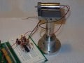
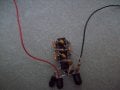
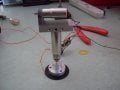
I built this circuit:

However, I am unsure about which orientation the four photodiodes should be placed in, and which motors to connect them to. Is it just guess and check?
However, I am unsure about which orientation the four photodiodes should be placed in, and which motors to connect them to. Is it just guess and check?