 Facebook
 Google
 GitHub
 Linkedin
Good day! I am making a battery monitor device. The device has to monitor 2 batteries in series, monitor the charging of each battery separately and of the 2 batteries toghether.
Specification: charger on 1 end with 14.7V, 20A. When the charger is disconnected the batteries will be connected to a load. The idea is to have a battery pack of 2 batteries at all times, connected in series, which I will monitor and later send the information to an MCU. There should be a defence against opposite connection (+ and - switched).
I have made these circuits.
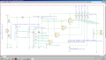
1. 12V monitor control - "Working.version.small.PCB.png".
What bothers me is: will the traces need to be too big in order for the fuse to burn first? Will 30A be enough for the diode "D1"?
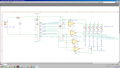
2. 24V monitor control (2 batteries in series) - "Medium.battery.monitor.circuit.png".
What bothers me is the same as before?
3. Diode control circuit - "Diode.version.battery.monitor.png".
Why is it not good to use the diode version circuit?
Specification: charger on 1 end with 14.7V, 20A. When the charger is disconnected the batteries will be connected to a load. The idea is to have a battery pack of 2 batteries at all times, connected in series, which I will monitor and later send the information to an MCU. There should be a defence against opposite connection (+ and - switched).
I have made these circuits.
1. 12V monitor control - "Working.version.small.PCB.png".
What bothers me is: will the traces need to be too big in order for the fuse to burn first? Will 30A be enough for the diode "D1"?
2. 24V monitor control (2 batteries in series) - "Medium.battery.monitor.circuit.png".
What bothers me is the same as before?
3. Diode control circuit - "Diode.version.battery.monitor.png".
Why is it not good to use the diode version circuit?
Attachments
-
 151.6 KB Views: 11
 -
 188 KB Views: 10
 -
 107.2 KB Views: 10
![IMG_20180322_144450[1].jpg](/data/attachments/136/136633-5b0ab4276406e7711f62921c6afa0a51.jpg)


