Battery charging protection for bench power supply

Thread Starter

greenisland

Joined Jan 7, 2020
93
Hello to everybody. I have not asked for any help in a while, but I have been observing from the sidelines, and have learnt a lot.
I built a variable power supply using the the Hiland kit, with the modifications suggested by Audioguro with very good success. (0-16v with max. 5 amp.)
I first built it on a breadboard to try to fully understand what was going on at each stage.

My question is this: I would like to use this bench supply for charging batteries and would like some back current protection in the circuit.
I know I could simply attach a big diode externally and add the diode drop to the bench supply output (I have charged a drill NiCd a few times this way, with constant current/voltage).
My fear is I will most likely do damage to this power supply someday in haste.
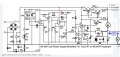
I am attaching a proposed mod. to the supply but have not been brave/stupid enough to test with a battery.

One other question maybe somebody could enlighten me on; protecting the supply if the battery was hooked up backwards, will this mod. do that?

I welcome and appreciate any help, advice.
Both D1 and D2 are large 10 amp diodes, A is ammeter.
 

Attachments

Last edited:

Thread Starter

greenisland

Joined Jan 7, 2020
93
Apology I should have drawn it in, I have it in now!
You're quite right, it should be there. I have altered this so many times, beginning with a much simpler op-amp circuit, it was positioned there originally and never thought to move it.
What protection would this offer if I connected the battery to a cold supply?
 

dl324

Joined Mar 30, 2015
18,395
I know I could simply attach a big diode externally and add the diode drop to the bench supply output (I have charged a drill NiCd a few times this way, with constant current/voltage).
This is the simplest solution. It protects D11 and C7 from batteries connected backwards and prevents discharge back to the input.

The best solution is to pay attention to what you're doing. You can only do so much to make things foolproof.
 

Thread Starter

greenisland

Joined Jan 7, 2020
93
Fuse will blow every time when excessive current flows through D11, hot or cold supply.
D11 needs to be capable of handling more than fuse, else D11 will burn.
ok, thanks, leave D1 there and reposition fuse?
What about hooking up the battery backwards?
 

Thread Starter

greenisland

Joined Jan 7, 2020
93
This is the simplest solution. It protects D11 and C7 from batteries connected backwards and prevents discharge back to the input.

The best solution is to pay attention to what you're doing. You can only do so much to make things foolproof.
Thanks for your help. Yes I know its impossible to make things totally idiot proof, and believe me I have tested this many times, but most car chargers have protection, don't they?, they know human nature.
Is D2 not doing the same job as an external diode?, I positioned it here to allow the op-amp to make up for the voltage drop.
 

Thread Starter

greenisland

Joined Jan 7, 2020
93
I don't know the circuit and the intention of D2 and D1.
Reversed power is very difficult to control, and therefore you should never take a chance with it. Fuse is just an example to have at least something on output.
Like dl324 said, use the diode on output to be absolutely sure when dealing with batteries.
Ok gents, understood and much appreciated.
Reposition fuse and attach diode externally when using as a charger.
 

dl324

Joined Mar 30, 2015
18,395
most car chargers have protection, don't they?
Most likely because I always connect the charger to the battery before plugging it in and I unplug the charger before disconnecting it from the battery. Unless the charger can be disconnected from the charger clips.
Is D2 not doing the same job as an external diode?
Yes, but I was referring to a situation where D1 and D2 weren't added. Presumably you have an external circuit to take care of charging the batteries, so the diode drop outside of the feedback loop would be a non-issue.
I positioned it here to allow the op-amp
What is the part number for U2?
 

Thread Starter

greenisland

Joined Jan 7, 2020
93
Thanks for your help Dennis,

I'm the same as you, I charged car batteries many times with commercial units and never once gave it a thought about the battery backfeeding current until a few months ago, I was reading online about a guy who damaged his bench power supply by connecting it to the battery first, before powering it up, he blew all the pass transistors.

I'm not a big charger freak, I have a few old nicd powered devices with missing chargers, (I don't know where half my stuff ends up; we have moved house a few times over the last few years and I swear every time somebody leaves a door open while on the move) I would not charge lipos with this supply.
It would be handy though to be able to use it without worry if needed.

All the op-amps are TLE2140, I am suppling only 23v dc to this circuit (the circuit shown supply is much higher) with -2v going to U3 (current regulator).

ARE D1 and D2 PROTECTING THE CIRCUIT OR WILL BEEFING UP D11 TO A 10 AMP DIODE WITH A 5 AMP FUSE NEAR THE POSITIVE POST ALONE DO THE JOB? as Juhahoo suggested.
 
Last edited:

Thread Starter

greenisland

Joined Jan 7, 2020
93
Thanks for your help Dennis,

I'm the same as you, I charged car batteries many times with commercial units and never once gave it a thought about the battery backfeeding current until a few months ago, I was reading online about a guy who damaged his bench power supply by connecting it to the battery first, before powering it up, he blew all the pass transistors.

I'm not a big charger freak, I have a few old nicd powered devices with missing chargers, (I don't know where half my stuff ends up; we have moved house a few times over the last few years and I swear every time somebody leaves a door open while on the move) I would not charge lipos with this supply.
It would be handy though to be able to use it without worry if needed.

All the op-amps are TLE2140, I am suppling only 23v dc to this circuit (the circuit shown supply is much higher) with -2v going to U3 (current regulator).

ARE D1 and D2 PROTECTING THE CIRCUIT OR WILL BEEFING UP D11 TO A 10 AMP DIODE WITH A 5 AMP FUSE NEAR THE POSITIVE POST ALONE DO THE JOB? as Juhahoo suggested.
Would this work as protection for charging a car lead acid battery?.
A large diode and 5 amp fuse in series at positive output terminal and a second diode placed on the sense loop re-directing any reverse current to ground ( seen on jpeg to the left of d11).
 

Attachments

Last edited:
Top