
I need help understanding out to implement this circuit. Will it work if I place it between a laptop headphone jack and my small “Pam xxx” mono amp. It is suppose to attenuate the treble so the bass will be “boosted.” See figure 3 in the uploaded file. Questions:
1. The left “IN” and left “Grn” are from my laptop headphone jack, correct?
2. I assume that the arrow for the Right “out” is from the pot to the amp as well as the right ground is connected to the left ground and then to the amp, correct?
I would like to change the values but I don't know how: The current components have a treble reduction range between 0 and 6 db but I would like for someone to tell me what new component value for the pot and for the resistor is needed to make the range 0 to 12db.
Maybe the explanation below (not mine) can help you but I don’t understand how to change those values. I assume that after I change the values to go from 0 to 12db, that the C1 value formula (starting HZ) will be the same or does that need to be changed too?.
Thanks
scott
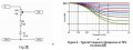
Variable Equalizer
The value of C1 is determined by the following (1/2 of the pot value is added to the resistor value, since both are in series, and a typical situation will have a pot setting of around halfway (note = that changes the starting frequency to begin the attenuation, ie 383 hz)
C1 = 1 / 2 * * (R1 + (VR1 / 2)) * f so an example = C1 = 1 / 2 * * 15k * 383 = 27nF
The only change that you will need is to the value of C1 according to the above formula.)
It is essential that the compensation circuit be driven from a low impedance source, and the load impedance should be reasonably high. There will be little error with loading above 20k, but basically the higher the impedance, the better. Opamp buffers at the input and output may be used if you cannot ensure that the source impedance is 100 ohms or less, and that the load impedance of the following stage is greater than 20k. My recommendation would be to use a buffer stage at the output with an input impedance of about 100k.
1. The left “IN” and left “Grn” are from my laptop headphone jack, correct?
2. I assume that the arrow for the Right “out” is from the pot to the amp as well as the right ground is connected to the left ground and then to the amp, correct?
I would like to change the values but I don't know how: The current components have a treble reduction range between 0 and 6 db but I would like for someone to tell me what new component value for the pot and for the resistor is needed to make the range 0 to 12db.
Maybe the explanation below (not mine) can help you but I don’t understand how to change those values. I assume that after I change the values to go from 0 to 12db, that the C1 value formula (starting HZ) will be the same or does that need to be changed too?.
Thanks
scott
Variable Equalizer
The value of C1 is determined by the following (1/2 of the pot value is added to the resistor value, since both are in series, and a typical situation will have a pot setting of around halfway (note = that changes the starting frequency to begin the attenuation, ie 383 hz)
C1 = 1 / 2 * * (R1 + (VR1 / 2)) * f so an example = C1 = 1 / 2 * * 15k * 383 = 27nF
The only change that you will need is to the value of C1 according to the above formula.)
It is essential that the compensation circuit be driven from a low impedance source, and the load impedance should be reasonably high. There will be little error with loading above 20k, but basically the higher the impedance, the better. Opamp buffers at the input and output may be used if you cannot ensure that the source impedance is 100 ohms or less, and that the load impedance of the following stage is greater than 20k. My recommendation would be to use a buffer stage at the output with an input impedance of about 100k.
Attachments
-
 24 KB Views: 20


