Basic Wiring Help :)

Thread Starter

n00by_123

Joined Aug 19, 2017
4
Hi,

I am looking for some super basic help and hoping this is the right place to post this..

I am working on a small home project to monitor water flow, but struggling with the wiring needed to get this up and running. I was hoping it would have been plug and play-ish, but that's not the case.

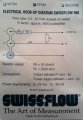
Ive attached a picture of what the wiring says on the box, but honestly dont have a clue where to start. I have looked all over for an image on how the wiring should look, and here is where my lack of wiring knowledge comes in ;)

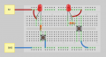
If someone could help draw a simpletons image of this, in something like Fritzling or circuits.io, I can give it a blast.

Thanks in advance for any help/pointers!
 

Attachments

AlbertHall

Joined Jun 4, 2014
12,619
What do you want to connect the flow meter to?
The output is a series of pulses withe frequency increasing with increased flow rate.
 

AlbertHall

Joined Jun 4, 2014
12,619
Do you want to know the flow rate (litres/minute or similar) or the total water used?
You need some sort of meter or display to be able get a reading of flow rate or total water used. A microcontroller and an LCD display would do it. Are you up to that?
 

Thread Starter

n00by_123

Joined Aug 19, 2017
4
Do you want to know the flow rate (litres/minute or similar) or the total water used?
You need some sort of meter or display to be able get a reading of flow rate or total water used. A microcontroller and an LCD display would do it. Are you up to that?

Thanks,

For now all I would like to do is just display the flow rate in the console - I was planning to use an Arduino or Pi.
 

AlbertHall

Joined Jun 4, 2014
12,619
The wiring for either goes like this:
Connect +5V from controller to the '+' terminal
Connect 0V from controller to the 'O' terminal
Connect a GPIO from controller to 'P' terminal
Connect a 2.2k resistor from '+' to 'P' - this is RL
You don't need RS.

The software needs a timer for 1 minute. During the minute count pulses and divide by 5600 and that gives you the flow rate in litres per minute.
 

Reloadron

Joined Jan 15, 2015
7,855
Thanks,

For now all I would like to do is just display the flow rate in the console - I was planning to use an Arduino or Pi.
Should you take the Arduino route Flow Rate Sensor Interfacing: How to Measure Liquid with an Arduino is a good read on the subject and includes the code which is well explained. Just keep in mind applying your K-Factor for your flow sensor. Your K-Factor being 5600 pulses per Liter.
Code:
// The hall-effect flow sensor outputs approximately 4.5 pulses per second per
// litre/minute of flow.
float calibrationFactor = 4.5;
You would change the 4.5 to your K-Factor of 5600 so your float calibrationFactor would = 5600.

Anyway, the link may be of dome value to you. You can measure flow as a Rate as in so many Liters Per Min or a Totalizer which would be total number of liters.

Use Albert's wiring scheme.

Ron
 

WBahn

Joined Mar 31, 2012
32,703
Why do you think that Rs isn't needed?

The instructions state that Rs should be 50Ω/V. If powered by 5 V, then that would indicate a 250 Ω resistor. I'm not sure how to interpret the 5 V / 20 mA note to the left of the resistor. It could mean that the voltage and current at that point should be 5 V at 20 mA -- in which case I would probably agree that no resistor is needed -- but that is not consistent with their directions.
 

AlbertHall

Joined Jun 4, 2014
12,619
Why do you think that Rs isn't needed?

The instructions state that Rs should be 50Ω/V. If powered by 5 V, then that would indicate a 250 Ω resistor. I'm not sure how to interpret the 5 V / 20 mA note to the left of the resistor. It could mean that the voltage and current at that point should be 5 V at 20 mA -- in which case I would probably agree that no resistor is needed -- but that is not consistent with their directions.
I interpreted that to mean 50Ω/V across Rs which, with a 5V supply, means zero ohms.
 

Reloadron

Joined Jan 15, 2015
7,855
I have also been wondering about that Rs and generally I see Rs to imply Resistance Shunt? Interesting you each interpret it differently. My initial take was that of Albert's. They also reflect a Power Requirement of 12 to 36 mA. Their data sheets seem to leave a little to be desired.

Ron
 
At 5V, your current limiting to 100 mA; about 10x what you need. It puts some of the power dissipation outside the device.

But then the formula of 50 ohms/V is weird. 240 Ohms at 24 V makes some sense and 50 at 5 V makes sense.
making Rs a suitably sized metal oxide resistor makes sense. Just limit the short circuit current to 100 mA.
Metal oxide resistors tend to totally break when overloaded.

Yep, the datasheet is nonsense.
 

WBahn

Joined Mar 31, 2012
32,703
At 5V, your current limiting to 100 mA; about 10x what you need. It puts some of the power dissipation outside the device.

But then the formula of 50 ohms/V is weird. 240 Ohms at 24 V makes some sense and 50 at 5 V makes sense.
making Rs a suitably sized metal oxide resistor makes sense. Just limit the short circuit current to 100 mA.
Metal oxide resistors tend to totally break when overloaded.

Yep, the datasheet is nonsense.
How on Earth do you come up with current limiting to 100 mA????

There is NOTHING that states a resistance value of 50 Ω. It clearly states 50 Ω per volt. I think AlbertHall has it correct, it is 50 Ω per volt that must be dropped across it in order to get 5 V at the pin when 20 mA is being drawn. So if you are using a 24 V supply, you have 19 V across Rs which then says it should be 950 Ω.
 

Alec_t

Joined Sep 17, 2013
15,103
I too would interpret it as meaning Rs needs to drop the supply voltage down to 5V at the sensor with a supply current of 20mA.
 

Thread Starter

n00by_123

Joined Aug 19, 2017
4
Hi All,

Thanks a lot for your quick replies!!!

I will give this a try when I get back home later this week and let you know how I get on :)

Thanks!!
 
Top