sorry guys, i must admit i know very little about filters, other than i need a bandpass filter, from 500hz to 3000hz, i was then hopeing to use a transitor to provide a switched output on the presence of a tone within the bandwidth specified
sorry about the lack of documentation, im a newbie at this
Then use a comparator to compare the output of the filter with a DC voltage and when the output of the filter is greater than the DC voltage the comparator will go high.
You if you set the bandwidth of the filter properly. However, remember that filters are not ideal they will pass frequencies near the bandwidth with a respectable amplitude.
One thing about your link Mike, I popped in some values and everything looked ok except R3, it calculated me a - value for resistance!? In other pages I found implementing the same filter, they just didn't have R3. Any reason it is there?
The ratio of (R4/R3) +1= gain of the opamp. Remove R3 then the opamp has no gain.
This extremely simple "bandpass" filters have almost no attenuation of outside signal frequencies. They attenuate frequencies you want because its cutoff frequencies are droopy and are not sharp.
The better filters I showed on the other website are "2nd-order" and have twice as much attenuation of outside signal frequencies as these 1st-order filters.
3rd-order and 4th-order filters are even better.
You asked why you can still hear 100Hz when the highpass filter is 4th-order. Of course, the attenuation is not much, you need 10th-order.
My gut says you would have better luck, more realistic component values and better circuit Q if you designed it in two stages, a lowpass active filter stage driving a highpass active filter. Most bandpass filter don't have to deal with such a wide bandpass as related to it's center frequency.
I was referring to Mike's circuit. -R2/R1 is the gain of the inverting amp. So what the is R3 doing? I found a site which had the same bandpass inverting filter but didn't have that R3 there.
The range you want to filter might be to large to have decent edges.
You could also use a lowpass filter of 3000 hz with a 300 hz highpass filter afther it.
what do you guys think of this circuit, a high pass filter followed by a low pass and then a comprator circuit. All i need to do is light the led when a tone between 500hz and 3khz is detected, however my maths isnt veryy good and i could do with some help on the values of components.
what do you think of the circuit design so far. I have been told it will need to run off two 9 volt batteries to provide a simple bi-polar power supply.
You will need to rectify afther the filters to have a DC voltage that you can compare with the DC reference.
What type of filters do you want to use ?
Depending on the resistor and capacitor values the filter will have different properties.
You will need to rectify afther the filters to have a DC voltage that you can compare with the DC reference.
What type of filters do you want to use ?
Depending on the resistor and capacitor values the filter will have different properties.
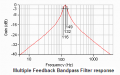
Mike's circuit is a simple narrow-bandwidth bandpass filter.
Your requirement has a bandwidth that is too wide for it.
At frequencies that you want high attenuation it barely has any attenuation.
Look it up in Google: Multiple Feedback bandpass filter Circuit
Your comparator compares the DC output voltage of the filter IC to the setting of the trimpot:
Turn the pot up and the LED lights.
Turn the pot down and the LED turns off.
You need to rectify the output of the filter, filter the pulses with a capacitor then drive a transistor with the result. The transistor will turn on the LED when there is a signal.
Opamps do not need a dual-polarity supply if their input is biased at half the supply voltage.
Mike's circuit is a simple narrow-bandwidth bandpass filter.
Your requirement has a bandwidth that is too wide for it.
At frequencies that you want high attenuation it barely has any attenuation.
Look it up in Google: Multiple Feedback bandpass filter Circuit

 Facebook
 Google
 GitHub
 Linkedin