Automatic chicken coop door project.

Thread Starter

shores487

Joined Jan 22, 2022
9
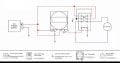
I’m a female and I am trying to build this automated hen door as seen for my husband as a surprise:

I was trying to do it following this schematic in the photo I found online (it’s unrelated to the video I posted. However, once I wired everything, it’s not working so I was hoping for some visual help.DC3ADD05-BCB8-4915-9159-E97C4AC2BE50.jpeg


Also, I don’t have the timer in the schematic, I had decided to use a photocell sensor instead. So it’s possible that’s my issue. Or perhaps my 8pin relay is somehow different then the one in the schematic. I am at a loss at this point.

3A670103-1E4F-43BD-A290-9842EA47A514.jpeg631F2CCA-D346-477D-AD05-FE8CF2930FE4.jpeg
I bought these parts:
Electromagnetic Power Relay, 8-Pin 10 AMP 12V DC Relay Coil with Socket Base, LED Indicator, DPDT 2NO 2NC - MY2NJ [Applicable for DIN Rail System] https://www.amazon.com/dp/B07T12WLM...t_i_Y838C3W0P8WPH6E7TNFZ?_encoding=UTF8&psc=1

ECO LLC 12 Inch 12" High Speed 14mm/s Linear Actuator Motor 1000N DC12V with Mounting Brackets and built in limiter https://www.amazon.com/dp/B07L7XCSD...t_i_P0HX9CAKX816ME60DRV8?_encoding=UTF8&psc=1

2 Pack - AC DC 12V 10A Auto On Off Photocell Light Switch Photoswitch Light Sensor Switch https://www.amazon.com/dp/B01M1O3C1...t_i_W577XCCANW7G1M7W261R?_encoding=UTF8&psc=1


12V Battery, HWE 12V 7Ah Lithium Battery, Deep Cycle 12V LiFePO4 Battery Built-in BMS Offer 4000 Cycles Life, for Small UPS, Solar Power, IOT, Kids Car, and Outdoor Camper https://www.amazon.com/dp/B095K38M6...t_i_PZPJ85D4RXBGTHH0FQS2?_encoding=UTF8&psc=1

Moderator edit: Thread title change to one that better reflects the content of the thread.
 

Attachments

ThePanMan

Joined Mar 13, 2020
773
Welcome to AAC. I see a couple problems:
1) your relay is wired wrong. The actuator should be tied to the two common pins. Unfortunately, the way it is drawn it appears the common pins are pins 3 & 4. Pins 5 & 6, where you have the actuator wired to - should be wired to pins 3 & 4; that is IF your drawing is correct.

2) If the actuator does not have limit switches then the actuator will try to run the motor in one direction or the other all day without being able to move. It'll eventually burn out. But while I'd assume it has limit switches, I wouldn't proceed without first verifying that it DOES have internal limit switches.

There's a third potential issue: If the motor draws more current than your light sensor can handle you'll burn that out too. It's likely the sensor has an internal relay, but again, I wouldn't proceed without first knowing for a fact that the motor and sensor relay are compatible.
 

Thread Starter

shores487

Joined Jan 22, 2022
9
Welcome to AAC. I see a couple problems:
1) your relay is wired wrong. The actuator should be tied to the two common pins. Unfortunately, the way it is drawn it appears the common pins are pins 3 & 4. Pins 5 & 6, where you have the actuator wired to - should be wired to pins 3 & 4; that is IF your drawing is correct.

2) If the actuator does not have limit switches then the actuator will try to run the motor in one direction or the other all day without being able to move. It'll eventually burn out. But while I'd assume it has limit switches, I wouldn't proceed without first verifying that it DOES have internal limit switches.

There's a third potential issue: If the motor draws more current than your light sensor can handle you'll burn that out too. It's likely the sensor has an internal relay, but again, I wouldn't proceed without first knowing for a fact that the motor and sensor relay are compatible.
Thank you! I tested the actuator and it does stop and does have limiter.
Also, would be able to provide a quick hand sketch of how it should be wired, including the photocell? It would be really helpful.
 

MisterBill2

Joined Jan 23, 2018
18,176
For the relay I suggest using an ohm meter or continuity tester to verify which terminals are the correct ones. The relay socket shown is not quite intuitive, unless they have changed it. And certainly the drawing is not quite right. The actuator needs ti be connected to the moving contact on the relay.
 

sghioto

Joined Dec 31, 2017
5,380
Also, would be able to provide a quick hand sketch of how it should be wired, including the photocell?
From the components listed it should be wired as below.
If the door operates in reverse then reverse the wires from the actuator to the relay pins 5 and 6.
EDIT: Added switches Sw1 and Sw2 to allow operating the door manually.
Standby current drain during the night time is appx 130ma total from the sensor and relay.
Standby current during daytime appx 5ma.
1643081339083.png
 
Last edited:

Thread Starter

shores487

Joined Jan 22, 2022
9
From the components listed it should be wired as below.
If the door operates in reverse then reverse the wires from the actuator to the relay pins 5 and 6.
EDIT: Added switches Sw1 and Sw2 to allow operating the door manually.
Standby current drain during the night time is appx 130ma total from the sensor and relay.
Standby current during daytime appx 5ma.
View attachment 258660
Thank you tons!!! Deeply appreciated!!!
 

Thread Starter

shores487

Joined Jan 22, 2022
9
Thank you tons!!! Deeply appreciated!!!
From the components listed it should be wired as below.
If the door operates in reverse then reverse the wires from the actuator to the relay pins 5 and 6.
EDIT: Added switches Sw1 and Sw2 to allow operating the door manually.
Standby current drain during the night time is appx 130ma total from the sensor and relay.
Standby current during daytime appx 5ma.
View attachment 258660
So, if I don’t put in the switches does the wire that is coming down to switch one get eliminated or does it just tie in directly to the other wire too?! Thanks!!
 

ThePanMan

Joined Mar 13, 2020
773
If that photo sensor is anything like the one I have - the red wire either connects positive power or not. When darkness falls the red wire goes active. You'll have to determine which way the actuator runs when the light condition changes.

As for the relay, the red wire on pin 3 should be moved to pin 5 and the black wire on pin 4 should be moved to pin 6. The blue wires from the actuator goes to pins 3 & 4. THAT IS IF the wiring diagram you've given is accurate. Like @MisterBill2 says, you need to verify which is which. Unless you have a diagram from somewhere that specifically relates to that relay.

Sorry I didn't get back to you sooner. I'm somewhat convalescing. I can stand to be at the computer for some few minutes then need to rest my bones. I may be the Pan Man but I'm not like the original Peter Pan - who never grows old.
 

sghioto

Joined Dec 31, 2017
5,380
As for the relay, the red wire on pin 3 should be moved to pin 5 and the black wire on pin 4 should be moved to pin 6. The blue wires from the actuator goes to pins 3 & 4. THAT IS IF the wiring diagram you've given is accurate.
The wiring diagram shown in my post is from the relay listed in post #1 and believed to be accurate from the photo of the relay.
It doesn't matter if the actuator leads or the power leads are connected to the common terminals.
1643155536554.png
 
Last edited:

ThePanMan

Joined Mar 13, 2020
773
sghioto
I'm not accustom to that symbology for the relay. After looking at it long and hard I now see that pins 5 & 6 are the common pins. That being the case then the TS has the right information.

Thanks for the clarity.

Just to point out the TS first drawing shows 3 & 4 being common. In that event the TS drawing was incorrect. I guess I just saw that depiction and ran with it.
 

MisterBill2

Joined Jan 23, 2018
18,176
Not as in a schematic but as a wiring diagram that the TS requested.
OK, but "sorry about that", I have been wiring things from circuit schematic for 60+ years and it is first nature for me. Wiire path maps! Did need to produce those so the tech folk could easily wire those big MS connectors.
 
Top