Facebook
 Google
 GitHub
 Linkedin
Hi all,
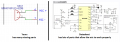
I have a project in which a ISD1616 audio recording chip is fed to a SIM808 chip mic input with a simple filter so that when the SIM808 makes a phone call, it will have an automated voice recorded message. The problem is that I get a bunch of static and no voice after I record. I don't know why that would be, other than I made a chinsy filter. Attached is my audio filter. The two green lines on the bottom go to the mic input on the SIM808. Any help is greatly appreciated!
Thanks,
Joe M
Attachments
-
 77.4 KB Views: 11