Attempt to repair a "non-repairable" shaving machine base

MrAl

Joined Jun 17, 2014
13,765
Hello.

I am back to this to try to do something out of this.
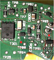
So, I'm still trying to figure out if the Shielded Gate Power Trench Mosfet is good or bad and I am not sure.
So, I'm doing the following test:
I'm powering the board with the normal 15V from an external power supply. Current is limited to 360mA, which is what the label of the SmartClean device says. 15V, 360mA.
Then, with a 2nd external power supply, I'm injecting 6V to the gate of this mosfet and measuring the voltage at the drain.
What happens is the following.
With the 15V power supply ON and 6V power supply OFF (Gate voltage injection), V_D = 15V.
With the 15V power supply ON and 6V power supply ON (Gate voltage injection), V_D = 15V.
Problem is that when the injection voltage of 6V is ON, the 15V power supply goes to CC mode (Constant Current) and the voltage drops from 15V to 0.77V and the current hits the limited value I set on the power supply of 360mA. However, the power supply doesn't activate the OCP (Over Current Protection mode), but there a shortcut clearly.

Is this a sign that the mosfet is bad?
Hi,

I am not exactly sure what you are doing there, but just to note when you test a MOSFET you have to know what kind it is to start with. With a bipolar you have to know if it is NPN or PNP, and with a MOSFET you have to know if it is a P MOSFET or N MOSFET. You also have to be very sure of what leads are which. For the bipolar we have to know the base, emitter, and collector leads, and for the MOSFET we have to know which leads are the gate, source, and drain. We have to be very certain of this information or else it may show up as being bad even if it is good, and we can also blow out the device if we switch two of the leads when we go to test it. If we blow out the device, there's no way to fix it except replace it and it only takes one single mistake to blow it out and then there is no going back except to buy a new transistor and replace the old one.

I made a mistake like this a long time ago with a bipolar. I accidentally mixed up the collector and emitter, and that meant that in the circuit there was too much reverse voltage across the base and emitter. The transistor still appeared to work with a simple test, but the Beta went way down so it would not work in the original circuit anymore. It was basically trash.
 

Thread Starter

PsySc0rpi0n

Joined Mar 4, 2014
1,786
Yes, I know about the pins. These mosfets packaging have 4 pins that are Drain, and on the opposite side they have 3 pins Source and 1 Gate.

I just removed the mosfet from the circuit and tried to turn it ON by using 2 external power supplies, one at 15V attached to Darin pins, a 10kΩ resistor between Gate and Source, Source connected to GND and then applying 8V to the gate and checking if the voltage at the drain would drop to 0V and after removing the 8V from the Gate, if the Drain voltage would go back uo to 15V, and they did, so I assume the mosfet is fine! I also checked the diodes around these area and they all read around 0.55V in Diode mode.

Don't know where else to go!
 

MrAl

Joined Jun 17, 2014
13,765
Yes, I know about the pins. These mosfets packaging have 4 pins that are Drain, and on the opposite side they have 3 pins Source and 1 Gate.

I just removed the mosfet from the circuit and tried to turn it ON by using 2 external power supplies, one at 15V attached to Darin pins, a 10kΩ resistor between Gate and Source, Source connected to GND and then applying 8V to the gate and checking if the voltage at the drain would drop to 0V and after removing the 8V from the Gate, if the Drain voltage would go back uo to 15V, and they did, so I assume the mosfet is fine! I also checked the diodes around these area and they all read around 0.55V in Diode mode.

Don't know where else to go!
Not sure if this was asked already, but do you have a schematic, or can create a schematic from the circuit board?
 

Thread Starter

PsySc0rpi0n

Joined Mar 4, 2014
1,786
Not sure if this was asked already, but do you have a schematic, or can create a schematic from the circuit board?
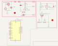
I don't have a schematic and I'm trying to create the schematic I can observe and I can measure with my DMM, but even so I may make mistakes. I'll post what I have right now.

1740130460480.png
1740129962318.png

So, this is what I have so far...

And in the schematic, there is a connection from a resistor (in section 2) to a pin of an STM chip that was crazy to get because it goes from top to bottom of the PCB several times through like 5 or 5 vias!

I'm now goign to try to work on the top of the PCB image circuitry and pass it to KiCAD!
 
Last edited:

MrAl

Joined Jun 17, 2014
13,765
I don't have a schematic and I'm trying to create the schematic I can observe and I can measure with my DMM, but even so I may make mistakes. I'll post what I have right now.

View attachment 342902
View attachment 342901

So, this is what I have so far...

And in the schematic, there is a connection from a resistor (in section 2) to a pin of an STM chip that was crazy to get because it goes from top to bottom of the PCB several times through like 5 or 5 vias!

I'm now goign to try to work on the top of the PCB image circuitry and pass it to KiCAD!
Hi,

Oh I see what you mean, this looks pretty complicated. I've done some complicated circuits too, but it takes time and patience and a lot of thought, and some verification with an Ohmmeter. It's also hard when their are IC chips that do not have any markings and are not familiar looking.

How much do these things cost if you had to buy a new one?
 

Thread Starter

PsySc0rpi0n

Joined Mar 4, 2014
1,786
Hi,

Oh I see what you mean, this looks pretty complicated. I've done some complicated circuits too, but it takes time and patience and a lot of thought, and some verification with an Ohmmeter. It's also hard when their are IC chips that do not have any markings and are not familiar looking.

How much do these things cost if you had to buy a new one?
Yes I'm using my DMM to try to figure out connections. It's not easy and probably there will be missing connections and some other that will be wrong. I'm still not very sure how to deal with inductors. Those maybe a bit more confusing to me.
So, if you people can help here and there when you see things that may not make sense, please let me know so that I can confirm the connection is correct or wrong. When the time comes for the inductors, I'll ask for help specifically for them.

Yeah, identifying components is another PITA but i'm also asking help for this in the web!
 
Top