Atmega AutoRange Ohmmeter

Thread Starter

Daniel Gouvêa

Joined Feb 19, 2025
28
First, I apologize for my poor English; I'm Brazilian and using automatic translation.

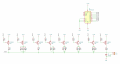
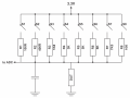
I'm designing a simple auto-ranging ohmmeter to test thermistors, and I'd like your help. This project requires a microcontroller, so I plan to use the ATmega328PB. I plan to use eight ranges for this measurement, with values chosen according to my points of interest.

A draft is below...
 

Attachments

Thread Starter

Daniel Gouvêa

Joined Feb 19, 2025
28
I'm sure everyone already understands the operating principle, but the idea is to close S1 to form a voltage divider between R1 and the DUT (device under test). Then, I open S1 and close S2, forming a voltage divider between R2 and the DUT, and so on. For each case, I measure the voltage generated by the divider using the Atmega ADC or an external ADC. Finally, I compare the values to identify which range was most suitable.

However, I need to save GPIO, as this circuit will be quadrupled, as I plan to test up to four thermistors simultaneously.
My initial idea is to use the SS8550 (PNP, SOT-23) instead of the switches. The range that will generate the most current is the first, and the worst case scenario would be with the output short-circuited, which would generate a current of 33 mA, disregarding the transistor's Vce. This value is within the capacity of this model. To save GPIO, I intend to use the PCF8574 as an I2C port expander, since the current sink capacity of this device is much more than enough to saturate the SS8550. The initial schematic would look like this...
 

Attachments

Aswinth

Joined Nov 1, 2016
34
Instead of using GPIO expander, you might wanna try using Shift Registers like 74HC595, especially if you want to save cost.
This IC is also called serial to parallel converter, and if you are using the Arduino IDE for programming your ATmega328P you code will also get simple.
Here is simple tutorial to get you started https://circuitdigest.com/microcontroller-projects/arduino-uno-shift-register-tutorial
The rest of the set will be same as shown in your PIC1
 

WBahn

Joined Mar 31, 2012
32,704
Is this some kind of academic project?

Is there a specific reason for you choice of those eight resistor values?

Since you want eight values, you could get that using just three I/O instead of eight. A couple of ways to do it. The simplest is to but four resistors in parallel with a switch in series with three of them. Then your MCU turns on some combination of them. This has another advantage in that you can have your MCU logic make three measurements to decide the best state of the three switches.

If you can't get acceptable resistance combinations that way, you could also but them in series or in series/parallel and try to find the closest set of values to your desired ones.

But your specific values shown are going to be hard to get particularly close to using this approach.

Another approach is to use an op-amp circuit to apply a current to the DUT that results in the desired voltage across it, then measure the current via a current-sense resistor.
 

Thread Starter

Daniel Gouvêa

Joined Feb 19, 2025
28
Instead of using GPIO expander, you might wanna try using Shift Registers like 74HC595, especially if you want to save cost.
This IC is also called serial to parallel converter, and if you are using the Arduino IDE for programming your ATmega328P you code will also get simple.
Here is simple tutorial to get you started https://circuitdigest.com/microcontroller-projects/arduino-uno-shift-register-tutorial
The rest of the set will be same as shown in your PIC1
Good suggestion. I will analyze the datasheet. Thanks for the idea.
 

Thread Starter

Daniel Gouvêa

Joined Feb 19, 2025
28
Is this some kind of academic project?

Is there a specific reason for you choice of those eight resistor values?

Since you want eight values, you could get that using just three I/O instead of eight. A couple of ways to do it. The simplest is to but four resistors in parallel with a switch in series with three of them. Then your MCU turns on some combination of them. This has another advantage in that you can have your MCU logic make three measurements to decide the best state of the three switches.

If you can't get acceptable resistance combinations that way, you could also but them in series or in series/parallel and try to find the closest set of values to your desired ones.

But your specific values shown are going to be hard to get particularly close to using this approach.

Another approach is to use an op-amp circuit to apply a current to the DUT that results in the desired voltage across it, then measure the current via a current-sense resistor.
It's for the company where I work. I'm an aircraft maintenance technician, and since I work with avionics, I started working in the electronics shop. I'm helping develop some test equipment.
 
Last edited:

Thread Starter

Daniel Gouvêa

Joined Feb 19, 2025
28
Is this some kind of academic project?

Is there a specific reason for you choice of those eight resistor values?

Since you want eight values, you could get that using just three I/O instead of eight. A couple of ways to do it. The simplest is to but four resistors in parallel with a switch in series with three of them. Then your MCU turns on some combination of them. This has another advantage in that you can have your MCU logic make three measurements to decide the best state of the three switches.

If you can't get acceptable resistance combinations that way, you could also but them in series or in series/parallel and try to find the closest set of values to your desired ones.

But your specific values shown are going to be hard to get particularly close to using this approach.

Another approach is to use an op-amp circuit to apply a current to the DUT that results in the desired voltage across it, then measure the current via a current-sense resistor.
A constant current source. The same operating principle as four-wire milliohmmeters. Perhaps this is a more interesting approach. I need to measure up to about 10KΩ. If I use an external ADC, such as the ADS1115, and use the 2.048V scale, I would need a current of 200uA (10KΩ x 200uA ≈ 2V). Is it easy to obtain such a low current with inexpensive components?
 

Thread Starter

Daniel Gouvêa

Joined Feb 19, 2025
28
I'll consider using the Texas REF200. It's significantly more expensive than the previous approach, but the circuit would be much simpler and likely more accurate. The dataset provides an exact example of what I need to do, as shown in the image below.
REF200.jpg
 

joeyd999

Joined Jun 6, 2011
6,204
If it were me, I'd design a precision programmable current source tied to addressable DUTs (using analog switches).

In this way, you could test any number of thermistors across a broad range of currents very quickly. The entire test process could be automated, and the tester could automatically choose the proper test current for each DUT, regardless of value.
It can even be made to self calibrate.
 
Top