are logic gates abstract entities or physical?

Adjuster

Joined Dec 26, 2010
2,148
Originally Posted by PG1995
I have heard the term "floating" in the context of electronics before. Perhaps, someone mentioned it while telling me how to operate a power supply, if I remember correctly. What does floating really mean? And what does really happen if it's floating?
The term "floating" in electrical contexts means isolated, not connected. In the context of a power supply this may refer to a complete circuit not having any connection to some other potential, such as mains ground. Thus "floating" power supply outputs might be connected in series without causing a short-circuit, whereas this cannot be done if they are all grounded.

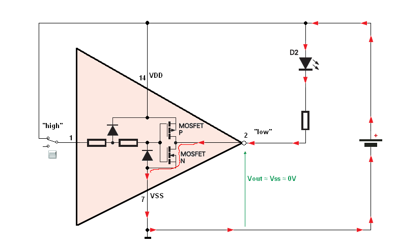
A floating logic input is simply open-circuit (not connected to a gate output, or anything else to define its level), although the common line feeding the gate may be grounded. The effect of leaving inputs open in this way depends on the technology used to make the gates: commonly this is an undesirable condition as the input level is not defined. This is particularly true for MOSFET inputs like CMOS, because they draw extremely low currents.

Sometimes a pull-up or pull-down resistor may be used to give a default condition to an input which is likely to be disconnected, to avoid the floating condition. Other technologies like TTL may have an inherent tendency to draw current input current in one direction, so that the input will more predictably take up one or other level.
 

Wendy

Joined Mar 24, 2008
23,421
Most cases you don't need a resistor, as with CMOS. TTL is an odd duck, if you leave an input open it assumes a high, it core to how that family works. CMOS can oscillate with an open input, and can (in rare circumstances) damage themselves.

In any case, don't leave inputs to logic open. The results can be unpredictable or worse.
 

Thread Starter

PG1995

Joined Apr 15, 2011
832
Thank you very much, everyone.

My question was:
In this diagram: http://img4.imageshack.us/img4/7324/jonydiagram2.jpg, Q4 is incomplete. I didn't realize it before. You have connected a LED followed by a resistor R2 to the output of a NOT gate (pin #12). I don't get it. In a gate the current flows from input to output. Therefore, how would the LED complete its circuit. Okay, after passing thru LED and R2 current enters the output but after that where does it go? I don't think LED should light up. Please help me with it.
The quoted part from Jony's post is reply to it.

And for example if we get inverter (NOT) gate and connect input node to positive terminal of a power supply.
So we have input at "high," or in a binary "1" state and the output is in "low" state or binary "0".


So output of a gate is sinking the current to provide a "0" or "low" state.
Vout is almost equal GND.
Ands as you can see the output current will flow for external power supply (pins 14 and 7)

1:
Please have a look on the linked diagram; it also has my question: http://img689.imageshack.us/img689/198/jonyinverter.png

2: In this diagram you have input of the gate at "0" and hence output at "1". The LED part is connected to the output at value "1" which is high potential. Would LED light up?

Please help me with the above queries. Thanks a lot.

Best wishes
PG
 

Adjuster

Joined Dec 26, 2010
2,148
How did you get the idea that logic gate outputs could only deliver current in one direction? In many cases, this is not true. Typically CMOS gates are capable of both directions according to the output state, as Jony's diagram shows. The amount of current available from CMOS devices may not always be enough to light LEDs very brightly, but there is no restriction to only source current.

Some gates do have "open-collector" or perhaps "open-drain" outputs. These can only pass current to one rail, but quite commonly this direction is down to negative.

If you look around you will find plenty of circuits which contain loads connected to positive rails and driven by gate outputs. This is a very common arrangement, and will work provided that the current and voltage ratings of the given output are respected. On the other hand, some gate outputs do not have enough current available to drive a bright LED or some heavier load like a relay or a motor. In this case, an external transistor may be used to increase the current capacity.
 

Jony130

Joined Feb 17, 2009
5,488

1:
Please have a look on the linked diagram; it also has my question: http://img689.imageshack.us/img689/198/jonyinverter.png
The gate output can easily sink (suck) the current when the output is in LOW state.
And if the output of the gate is in the high state, the output can source (deliver) the current into the output terminal.
See the example


2: In this diagram you have input of the gate at "0" and hence output at "1". The LED part is connected to the output at value "1" which is high potential. Would LED light up?
If the output is high state the LED is OFF ( no light).
You need to output go Low ("0") to light the LED.
So you need to press (push) S1 button.
By pressing S1 button the gate see "1" on the input so the output will be in low state ("0").
So the LED will light as long as S1 button is pressed.

See the simulation file from Circuit Wizard
 

Attachments

Thread Starter

PG1995

Joined Apr 15, 2011
832
Thanks a lot, Adjuster, Jony.

@Jony: That Circuit Wizard file was very simple and helpful. I now like CW more than MultiSim, the way it shows current flow and voltage levels is very helpful feature for beginner and slow learners like me. Thank you for that.

I had the concept of logic gates all wrong. Now I realize this. As an example take NOT gate: http://img835.imageshack.us/img835/6624/notgate.gif

There is a pump at the center. Whether the pump would suck/sink the current away from the output B or compress/push the current toward the output B is determined by the 'logic level' at the input A. It's a kind of bi-directional pump. I hope I have it correct now.

Thank you very much all of you. I'm much obliged.

Best wishes
PG
 

Adjuster

Joined Dec 26, 2010
2,148
Actually, there is at least one type of logic gate which does involve current paths from input to output, namely diode logic: http://en.wikipedia.org/wiki/Diode_logic

This however can have only limited application, as the gate output levels are degraded compared to their inputs.

Practical systems of any complexity require amplification to overcome such losses, as in the (now obsolete) diode-transistor logic (DTL). http://en.wikipedia.org/wiki/DTL
 

Thread Starter

PG1995

Joined Apr 15, 2011
832
Actually, there is at least one type of logic gate which does involve current paths from input to output, namely diode logic: http://en.wikipedia.org/wiki/Diode_logic

This however can have only limited application, as the gate output levels are degraded compared to their inputs.

Practical systems of any complexity require amplification to overcome such losses, as in the (now obsolete) diode-transistor logic (DTL). http://en.wikipedia.org/wiki/DTL
Thank you, Adjuster. Actually, this kind of information many a time plays an important role. Someone might ask you about a logic gate which only lets the current from input to output.

Best wishes
PG
 

thatoneguy

Joined Feb 19, 2009
6,359
Thank you, Adjuster. Actually, this kind of information many a time plays an important role. Someone might ask you about a logic gate which only lets the current from input to output.

Best wishes
PG
Current never flows back to the input in a modern logic gate. Gates, specifically buffers and inverters use the same symbol as an amplifier for a reason. With all common logic families, once the input crosses the threshold voltage going up, the output is pulled to either Full High or Full Low (values are historically 5V and GND, but can be as little as 0-1V in CPUs, or 0-15V with CMOS).

The non "open collector" CMOS gates have Totem Pole outputs, which means there are two transistors connected to the output. These are controlled by what is on the input, this is one technique of amplification to the +5V logic level when there is only a 3.5V input on a buffer, for example.

The reason you need to tie unused CMOS inputs to Vdd or Vss is the input impedance is so low that wires on a breadboard (or even the IC pins) can act as RF Antennas and spurious signals will cause the gates to switch randomly at high frequencies. If you are only using 1 gate on an IC with 4, having 3 oscillating is bad since all 4 are run from the same power supply. This will cause the one gate you are using to not have a solid +V logic output, as much power is drawn when CMOS gates are in transition.

Actually, another benefit of CMOS is that the circuit only uses current during transitions, which has ridden us of physical Power Switches in many things, such as remote controls, etc. There are ways to use a "soft power on" without using CMOS, but the low current draw is a big benefit. If your 3Ghz CPU was somehow made with TTL logic rather than CMOS, it would dissipate enough heat to cook a turkey. :D
 
Top